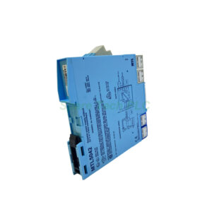
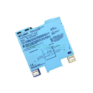
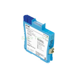
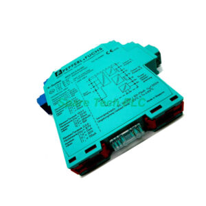
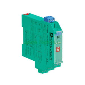
MTL5044 Isolated Transmitter Repeater for Hazardous and Safe Areas
Product Introduction
The MTL5044 delivers a fully-floating DC supply for two transmitters located in hazardous areas. Each channel powers a conventional 2-wire 4/20mA device. Meanwhile, the module repeats the same current through two floating output circuits. These outputs drive loads installed in safe areas.
For instance, the hazardous-area input accepts 0 to 24mA including over-range. At 20mA, the transmitter voltage reaches 16.5V. The safe-area output provides a signal range of 4 to 20mA. Additionally, the output supports 0 to 24mA for over/under range conditions.
Key Technical Specifications
The safe-area load resistance ranges from 0 to 550Ω. Moreover, the safe-area circuit output resistance stays above 2MΩ. Ripple in the safe-area circuit measures less than 125µA peak-to-peak.
Transfer accuracy at 20°C is better than 20µA. Typically, you can expect 5µA. Temperature drift remains below 1µA/°C. Response time settles to within 10% of the final value in under 250µs.
Therefore, the MTL5044 ensures precise signal reproduction even in fast-changing processes. The green LED indicates power is on. Supply voltage range is 20 to 35V dc.
Power and Current Consumption
Maximum current consumption with two 20mA signals is 110mA at 24V. At 20V, it draws 130mA. At 35V, it draws 80mA. Maximum power dissipation inside the unit reaches 1.5W at 24V with two 20mA signals.
Safety Description and Approvals
Safety description: 28V, 300Ω, 93mA; Um = 250V rms or dc. The MTL5044 suits Zone 0, IIC, T4–6 hazardous areas if certified accordingly. It also works in Div. 1, Group A hazardous locations.
Terminal Functions for Easy Wiring
Channel 1 uses terminals 1 (input –ve) and 2 (input +ve). Channel 2 uses terminals 4 (input –ve) and 5 (input +ve). For outputs, channel 2 connects to terminals 8 (–ve) and 9 (+ve). Channel 1 outputs use terminals 11 (–ve) and 12 (+ve). Power connects to terminal 13 (–ve) and terminal 14 (+ve).
This clear terminal arrangement reduces wiring errors during installation. Furthermore, it speeds up maintenance and troubleshooting.
Mechanical and Environmental Parameters
Operating temperature range is –20°C to +60°C. Storage temperature goes from –40°C to +80°C. Humidity tolerance is 5 to 95% non-condensing. The housing material is polyamide with a flammability rating of V0. Mount the unit on a standard 35mm DIN rail.
Installation Guidelines
First, disconnect all power before installation. Next, mount the MTL5044 securely on the DIN rail inside a suitable enclosure. Then, connect hazardous-area transmitters to input terminals 1, 2 and 4, 5. After that, wire safe-area loads to output terminals 8, 9 and 11, 12. Finally, apply 20 to 35V dc to terminals 13 and 14.
Check that the green LED lights up. Ensure cable segregation between hazardous and safe-area circuits. Use approved barriers if local codes require them.
Packaging List
Shipping Information
All orders ship via Fedex, UPS, or DHL. Delivery typically takes 3–7 business days depending on destination.
FAQ
1. Can the MTL5044 work with smart transmitters?
Yes, it supports conventional 2-wire 4/20mA transmitters. For HART communication, use a separate HART interface because the MTL5044 does not actively pass HART signals.
2. What happens if the safe-area load exceeds 550Ω?
The output voltage may drop below the required level. Consequently, the loop current will no longer represent the process value accurately.
3. Does the MTL5044 require an external power supply?
Yes, it needs a 20 to 35V dc supply connected to terminals 13 and 14. The green LED confirms power is present.
4. Can I use only one channel on the MTL5044?
Absolutely. Leave the unused channel inputs unconnected. Power consumption will be lower than the two-channel maximum values.
5. Is the MTL5044 suitable for SIL-rated applications?
Refer to the full safety manual for SIL certification details. The MTL5044 meets basic isolation requirements but check your system’s SIL level needs.