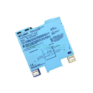
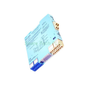
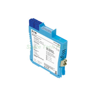
MTL5042 2/3-Wire Transmitter Power Supply with Comms
Product Introduction
The MTL5042 provides a fully-floating DC supply for energizing conventional 2-wire or 3-wire 4/20mA transmitters in hazardous areas. It then repeats the same current signal to drive a safe-area load. For smart 2-wire transmitters, this module allows bi-directional digital communications superimposed on the 4/20mA signal.
Specifically, the MTL5042 supports HART, Honeywell DE, Foxboro, and Yokogawa Brain protocols. The digital signal bandwidth spans from 10Hz to 12kHz. This makes the module ideal for modern smart instrumentation.
Additionally, this unit delivers outstanding performance. Transfer accuracy at 20°C stays better than 10µA. Temperature drift remains below 0.5µA/°C. Response time settles to within 10% of final value in just 40µs – significantly faster than the standard MTL5041.
Technical Specifications
Input (Hazardous Area)
Signal range: 0 to 24mA (including over-range)
Transmitter voltage: 16.5V at 20mA
Input terminal functions:
Output (Safe Area)
Signal range: 4 to 20mA (normal), 0 to 24mA (under/over-range)
Load resistance: 0 to 600Ω
Output resistance: >2MΩ (floating circuit)
Ripple: <40µA peak-to-peak
Performance Specifications
Number of channels: 1
Transfer accuracy at 20°C: Better than 10µA
Temperature drift: <0.5µA/°C
Response time: Settles within 10% of final value under 40µs
Digital Communication Support
Power Supply Requirements
Supply voltage: 20 to 35V DC
Current consumption (with 20mA signal):
75mA at 24V
85mA at 20V
55mA at 35V
Power dissipation (with 20mA signal): 1.3W at 24V
Indicators and Terminals
LED indicator: Green (power indication)
Optional HHC terminals (Hazardous Area):
Terminal 4: Optional HHC –ve
Terminal 5: Optional HHC +ve
Terminal 8: Optional HHC –ve
Terminal 9: Optional HHC +ve
Note: These require a HAZ4-6 connector
Safe area terminals: Terminals 11 (output –ve) and 12 (output +ve) require a SAF7-9 connector
Supply terminals: Terminal 13 (supply –ve), Terminal 14 (supply +ve)
Hazardous Area Approvals
The MTL5042 supports transmitters located in:
Zone 0, IIC, T4-6 hazardous areas (with suitable certification)
Division 1, Group A hazardous locations
Safety Descriptions
Terminals 2 to 1 and 3: 28V, 300Ω, 93mA; Um = 250V rms or DC
Terminals 1 to 3: Non-energy-storing apparatus ≤1.2V, ≤0.1A, ≤20µJ and ≤25mW. These can be connected without further certification into any IS loop with an open-circuit voltage <28V
Important note: Terminals 1 and 3 only support HART communications in one direction – from field device to safe-area connections 11 and 12.
Key Features and Benefits
Smart Transmitter Communication
The MTL5042 stands apart from basic isolators because it passes digital signals. HART, Honeywell DE, Foxboro, and Yokogawa Brain protocols all work through this module. Your smart transmitters remain fully accessible from the safe area.
Ultra-Fast Response Time
With a 40µs settling time, this module tracks the fastest process changes. Control loops respond almost instantly. Therefore, the MTL5042 excels in high-speed applications like flow or pressure control.
Exceptional Accuracy
Typical transfer accuracy of 10µA (or better) preserves your measurement integrity. Temperature drift of 0.5µA/°C means minimal error across ambient temperature swings. Your process data stays reliable year-round.
Flexible Transmitter Support
The MTL5042 powers both 2-wire and 3-wire transmitters. For 3-wire devices, use the appropriate terminal configuration. This flexibility reduces spare part inventory requirements.
Wide Load Range
The safe-area output drives loads from 0 to 600Ω. This range covers most PLC analog inputs, DCS cards, and panel meters. No extra signal conditioning is typically necessary.
Installation Guidelines
First, mount the MTL5042 in a safe-area enclosure. Connect a 20-35V DC power supply to terminals 13 (negative) and 14 (positive). The green LED should illuminate to confirm power.
For a standard 2-wire smart transmitter, connect:
Terminal 2 (transmitter supply +ve) to transmitter positive
Terminal 1 (current input) from transmitter negative
Terminal 3 (common) as the return path
For the safe-area output, connect your load (0-600Ω) to terminals 11 (output –ve) and 12 (output +ve). Use a SAF7-9 connector for these terminals.
For HART communication, connect your HART modem across the load or directly to terminals 11 and 12. Communications flow bi-directionally for 2-wire transmitters.
Terminal Connection Summary
Packaging List
Note: No connectors, terminal blocks, HHC cables, certificates, or warranty documents are included in the package.
Shipping Information
We ship this module via FedEx, UPS, or DHL. All shipments include tracking and basic insurance.
Frequently Asked Questions (FAQ)
1. What is the main difference between MTL5042 and MTL5041?
The MTL5042 adds bi-directional digital communication support (HART, Honeywell DE, Foxboro, Yokogawa Brain). It also offers faster response (40µs vs 250µs) and better accuracy (10µA vs 20µA). However, its load capacity is lower (600Ω vs 1kΩ).
2. Can the MTL5042 work with 3-wire transmitters?
Yes, this module supports both 2-wire and 3-wire 4/20mA transmitters. For 3-wire devices, connect the transmitter's common to terminal 3 and use the appropriate power wiring. Refer to the product manual for exact 3-wire connections.
3. Does the MTL5042 support HART communication in both directions?
For 2-wire transmitters, yes – HART communicates bi-directionally. However, terminals 1 and 3 only support HART in one direction (from field device to safe area). For full bi-directional HART, use the main 4/20mA loop connections.
4. Why do terminals 4,5,8,9 require special connectors?
These optional HHC (Handheld Communicator) terminals need a HAZ4-6 connector to maintain intrinsic safety ratings. Standard terminal blocks may compromise hazardous area approvals. Always use MTL-approved accessories.
5. What happens if I exceed 600Ω on the safe-area output?
The MTL5042 cannot drive loads above 600Ω while maintaining the full 4-20mA range. Excessive load resistance will limit output current and cause signal errors. Use an input card with lower impedance or add a signal splitter.