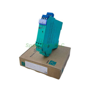
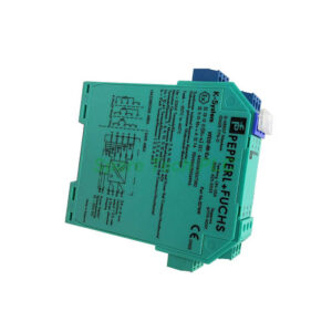
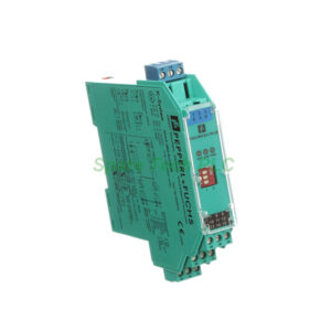
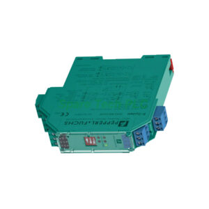
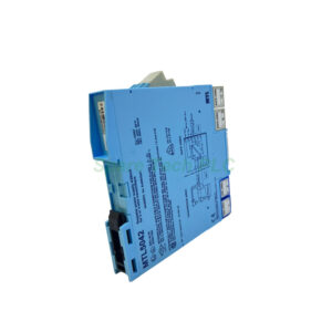
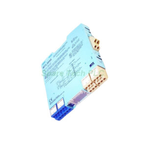
MTL5041 Hazardous Area Transmitter Power Supply 1-Ch
Product Introduction
The MTL5041 supplies DC power to conventional 2-wire 4/20mA transmitters installed in hazardous areas. It also repeats the same current signal to a floating circuit for safe-area loads. This module creates a fully isolated barrier between hazardous and safe locations.
Specifically, the MTL5041 supports transmitters in Zone 0, IIC, T4-6 hazardous areas or Div.1, Group A locations. The safe-area output drives loads from 0 to 1kΩ. Its hazardous-area input provides 16.5V at 20mA to the transmitter.
Additionally, this unit delivers excellent accuracy. Transfer accuracy at 20°C stays better than 20µA (typically 5µA). Temperature drift remains below 1µA/°C. Response time settles to within 10% of final value in just 250µs.
Technical Specifications
Input (Hazardous Area)
Signal range: 0 to 24mA (including over-range)
Transmitter voltage: 16.5V at 20mA
Safety description: 28V, 300Ω, 93mA; Um = 250V rms or DC
Output (Safe Area)
Signal range: 4 to 20mA (normal), 0 to 24mA (over/under-range)
Load resistance: 0 to 1kΩ
Output resistance: >2MΩ (floating circuit)
Ripple: <125µA peak-to-peak
Performance Specifications
Number of channels: 1
Transfer accuracy at 20°C: Better than 20µA (typically 5µA)
Temperature drift: <1µA/°C
Response time: Settles within 10% of final value under 250µs
Power Supply Requirements
Supply voltage: 20 to 35V DC
Current consumption (with 20mA signal):
70mA at 24V
85mA at 20V
55mA at 35V
Power dissipation (with 20mA signal): 1.2W at 24V
Indicators and Terminals
Hazardous Area Approvals
The MTL5041 is designed for:
Zone 0, IIC, T4-6 hazardous areas (with suitable certification)
Division 1, Group A hazardous locations
The safety description is 28V, 300Ω, 93mA with Um = 250V rms or DC. Always verify your specific hazardous area certification before installation.
Key Features and Benefits
Fully-Floating Isolation
The MTL5041 provides complete galvanic isolation between the hazardous-area input and safe-area output. This floating design eliminates ground loops. It also protects safe-area equipment from fault currents.
High Transfer Accuracy
With typical accuracy of 5µA, this module preserves your 4/20mA signal integrity. Even at temperature extremes, drift stays below 1µA/°C. Your process measurements remain reliable across varying conditions.
Fast Response Time
The 250µs settling time allows this module to track rapidly changing process variables. Control loops respond quickly without signal lag. Therefore, the MTL5041 works well for high-speed applications.
Wide Load Range
The safe-area output drives loads from 0 to 1kΩ. This wide range accommodates most PLC inputs, indicators, and recorders. No additional signal conditioning is normally required.
Installation Guidelines
First, mount the MTL5041 in a safe-area enclosure. Connect terminals 13 and 14 to a 20-35V DC power supply. The green LED should illuminate to confirm power.
Next, wire your hazardous-area 2-wire transmitter to terminals 1 (negative) and 2 (positive). The module provides 16.5V at 20mA to power the transmitter. Then, connect your safe-area load (0-1kΩ) to terminals 11 (negative) and 12 (positive).
Finally, verify all wiring complies with local hazardous area regulations. Use appropriate cable glands and sealing methods for Zone 0 or Div.1 installations. The MTL5041 safety description (28V, 300Ω, 93mA) must not be exceeded.
Terminal Connection Summary
Packaging List
Note: No terminal blocks, wiring accessories, certificates, or warranty documents are included in the package.
Shipping Information
We ship this module via FedEx, UPS, or DHL. All shipments include tracking and basic insurance.
Frequently Asked Questions (FAQ)
1. Can the MTL5041 power a 3-wire or 4-wire transmitter?
No, this module is specifically designed for 2-wire 4/20mA transmitters. For 3-wire or 4-wire devices, consider a different MTL model with additional power and return channels.
2. What happens if my safe-area load exceeds 1kΩ?
The MTL5041 output cannot drive loads above 1kΩ while maintaining the 4-20mA range. Excessive load resistance will limit current and cause signal errors. Use a load resistor or input card with lower impedance.
3. How do I interpret the safety description 28V, 300Ω, 93mA?
These values represent the maximum output parameters under fault conditions: 28V open-circuit voltage, 300Ω equivalent resistance, and 93mA short-circuit current. This description certifies the module for intrinsic safety applications.
4. Is the green LED the only status indicator?
Yes, the green LED simply confirms power is applied. The MTL5041 does not include a channel status or fault LED. Check your 4/20mA loop externally for signal verification.
5. Can I use this module for 0-20mA signals instead of 4-20mA?
Yes, the MTL5041 passes 0 to 24mA including over/under-range. For 0-20mA operation, simply connect your transmitter accordingly. The transfer accuracy and response time remain the same.