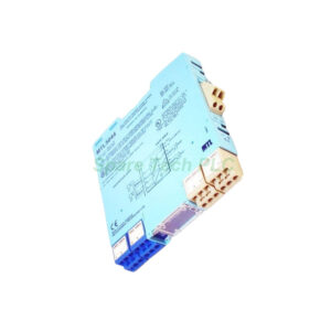
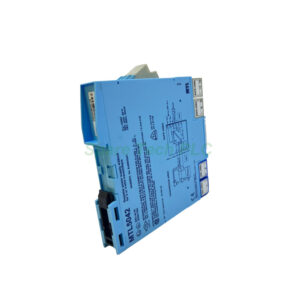
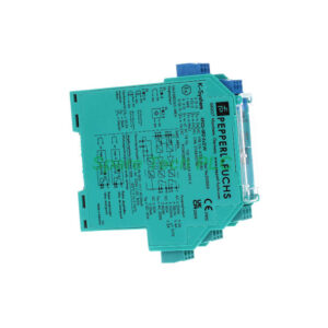
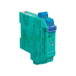
MTL5040 Two-Channel Isolated Transmitter Repeater and Driver
Product Introduction
The MTL5040 provides a fully floating DC supply for one 2-wire 4/20mA transmitter located in a hazardous area. Channel 1 repeats the transmitter current through a floating circuit to drive a safe-area load. Meanwhile, Channel 2 accepts a 4/20mA or 0/20mA signal from a safe-area controller. Then it drives a load in the hazardous area.
Therefore, this single unit solves two common isolation needs. First, it transmits sensor signals out of hazardous zones. Second, it sends control signals into hazardous zones. Both channels operate independently.
Channel 1 – Transmitter (Analog Input) Specifications
For Channel 1, the safe-area output signal ranges from 4 to 20mA. Over/under range extends from 0 to 24mA. Safe-area load resistance must stay between 0 and 550Ω. Additionally, the safe-area circuit output resistance exceeds 2MΩ.
On the hazardous side, the input accepts 0 to 24mA including over-range. At 20mA, the transmitter voltage reaches 16.5V. This ensures most 2-wire transmitters receive adequate power.
Channel 2 – Driver (Analog Output) Specifications
Channel 2 receives a safe-area input signal from 4 to 20mA. Over/under range covers 0 to 24mA. The hazardous-area output drives a maximum load resistance of 550Ω, which equals 11V at 20mA.
Furthermore, the hazardous-area circuit output resistance stays above 2MΩ. Input voltage drop measures less than 4V at 20mA. Both input and output circuits show ripple below 40µA peak-to-peak.
Accuracy, Drift, and Response Time
Transfer accuracy at 20°C is better than 20µA. Typically, you can expect 5µA. Temperature drift remains under 1µA/°C for the 4 to 20mA range. Response time settles to within 10% of the final value within 250µs typically.
Consequently, the MTL5040 delivers reliable performance in temperature-varying environments. Fast response makes it suitable for control loops requiring quick updates.
Power Supply and Consumption
Supply voltage ranges from 20 to 35V dc. The green LED indicates power is on. Maximum current consumption with a 20mA signal is 95mA at 24V. At 20V, it draws 110mA. At 35V, it draws 70mA.
Maximum power dissipation inside the unit reaches 1.6W at 24V and 1.8W at 35V with a 20mA signal. This low dissipation reduces heat buildup in enclosures.
Isolation and Safety Approvals
Isolation rating is 250V ac between safe circuits, hazardous circuits, and the power supply circuit. Safety description: 28V, 300Ω, 93mA; Um = 250V rms or dc.
The MTL5040 suits Zone 0, IIC, T4–T6 hazardous areas if suitably certified. It also works in Div. 1, Group A hazardous locations.
Terminal Functions for Clear Wiring
Channel 1 (transmitter) uses terminal 1 (input –ve) and terminal 2 (input +ve). Its output uses terminal 11 (–ve) and terminal 12 (+ve). Channel 2 (driver) uses terminal 4 (output –ve) and terminal 5 (output +ve) for the hazardous side. Its safe-area input uses terminal 8 (–ve) and terminal 9 (+ve). Power connects to terminal 13 (–ve) and terminal 14 (+ve).
This logical terminal grouping minimizes wiring mistakes. Moreover, it simplifies panel documentation.
Mechanical and Installation Information
Mount the MTL5040 on a standard 35mm DIN rail. Operating temperature range is –20°C to +60°C. Storage temperature goes from –40°C to +80°C. Humidity tolerance is 5 to 95% non-condensing.
First, disconnect all power before installation. Next, secure the unit on the DIN rail. Then wire hazardous-area devices to the appropriate terminals. After that, connect safe-area controllers and loads. Finally, apply 20–35V dc to terminals 13 and 14. Always segregate hazardous and safe-area wiring.
Packaging List
Shipping Information
All orders ship via Fedex, UPS, or DHL. Delivery typically takes 3–7 business days.
FAQ
1. Can the MTL5040 handle both input and output signals simultaneously?
Yes. Channel 1 reads a transmitter from the hazardous area. Channel 2 drives a load in the hazardous area. Both channels work independently at the same time.
2. What happens if I apply a 0/20mA signal to Channel 2?
The MTL5040 accepts 0 to 24mA on Channel 2 input. Therefore, a 0/20mA signal works perfectly. The hazardous-area output will follow the input linearly.
3. Does the MTL5040 support HART communication?
It supports conventional 4/20mA signals. For HART, use a separate HART interface because the MTL5040 does not actively pass HART frequencies.
4. Can I use only one channel on the MTL5040?
Absolutely. Leave the unused channel terminals disconnected. Power consumption will be lower than the two-channel maximum values shown.
5. What is the maximum cable length for the hazardous-area output?
The maximum load resistance is 550Ω. Calculate your cable length based on wire resistance. For example, 22 AWG wire at 0.053Ω/m allows roughly 10,000 meters loop length.