Home /
Products /
ATV930D37N4 | Schneider Electric 37 kW Variable Speed Drive
ATV930D37N4 | Schneider Electric 37 kW Variable Speed Drive
ATV930D37N4
Manufacturer: N/A Series: N/A Model Number: ATV930D37N4 Weight: N/A Condition: In Stock Availability: 100% Original Brand New Product Origin: U.S.A Shipping port: Xiamen Warranty: 12 Month
Why the ATV930D37N4 Belongs on Your Process Line
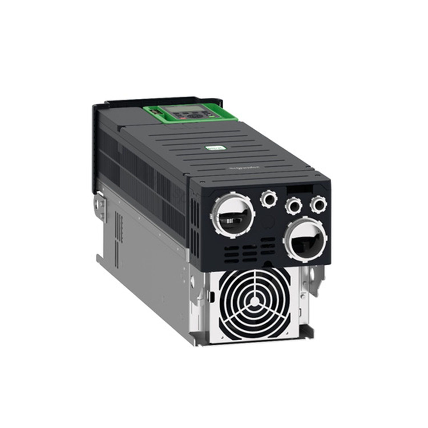
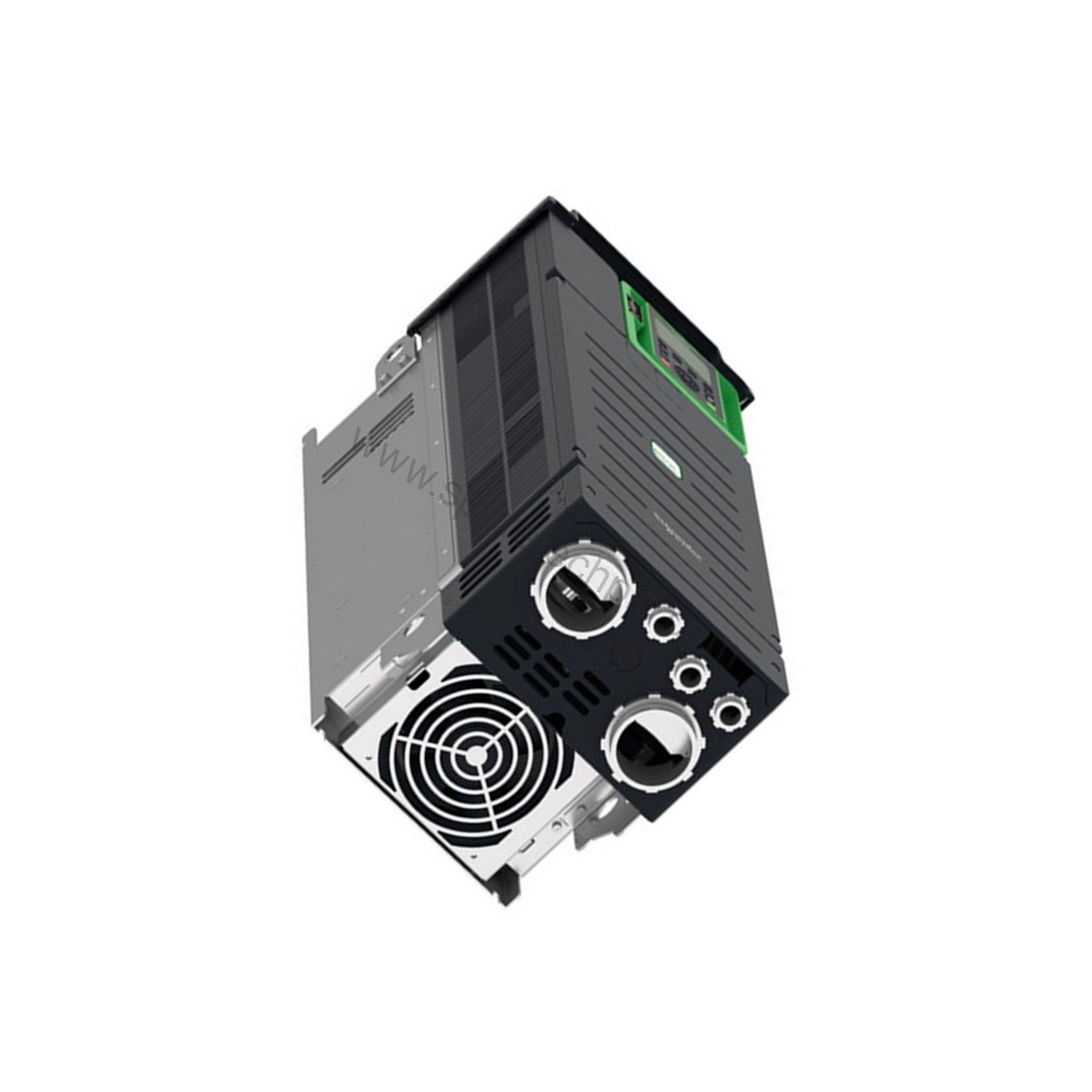
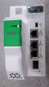
Downtime on a process line rarely waits for a purchase order. The Schneider Electric ATV930D37N4 is a 37 kW variable speed drive from the Altivar Process ATV900 range, built for industrial applications that cannot afford a stalled motor. It controls asynchronous and synchronous motors, ships with an integrated braking chopper, and mounts directly to the wall in an IP21 enclosure.
This is a drive designed for process duty, not light commercial work. With 74.5 A continuous output at 4 kHz normal duty and 61.5 A at heavy duty, it holds its rating under real load.
Discrete inputs: 10 (DI1...DI8 programmable, plus STOA/STOB safe torque off)
Analogue inputs: 3, software-configurable 0...10 V DC or 0...20 mA / 4...20 mA
Dimensions: 226 mm W x 673 mm H x 271 mm D; weight 28.2 kg
Solving Real Engineering Pain Points
Pain point one: motors that coast when they should stop
On high-inertia loads, a drive without braking capability lets the motor drift. The ATV930D37N4 integrates a braking chopper, so deceleration energy dissipates through a resistor instead of tripping the drive on DC bus overvoltage. That matters on centrifuges, winders, and any application where stopping position is part of the process.
Pain point two: network mismatch
Plant networks are rarely uniform. This drive speaks Modbus TCP, Modbus serial, and EtherNet/IP natively through two RJ45 ports and a 2-wire RS 485 interface. Slot A accepts optional communication modules for Profibus DP V1, PROFINET, DeviceNet, EtherCAT, CANopen, and Ethernet Powerlink, so you can match the drive to the existing control architecture rather than rebuilding the network around it.
Pain point three: safety without extra hardware
The ATV930D37N4 includes Safe Torque Off (STO), Safely Limited Speed (SLS), Safe Stop 1 (SS1), and Safe Brake Management (SBC/SBT). These functions reduce the need for external safety relays on many machine designs.
Installation Notes
Mount the drive vertically, within +/- 10 degrees, on a wall with adequate clearance for the 240 m3/h cooling airflow. Power terminals accept 35...50 mm2 (AWG 3...AWG 1) on the line and motor side; the DC bus takes 25...50 mm2 (AWG 4...AWG 1). Control wiring uses screw terminals for 0.5...1.5 mm2 (AWG 20...AWG 16).
Operating altitude is up to 1000 m without derating; above that, apply 1 % current derating per 100 m up to 4800 m. Ambient operating temperature is -15...50 degrees C without derating, and 50...60 degrees C with a derating factor.
Selection and Availability
Before ordering, confirm your motor's normal-duty or heavy-duty current requirement against the 74.5 A and 61.5 A figures, and verify the network protocol your controller expects. SpareTech Plc provides expert technical selection support to match the ATV930D37N4 to your application. Please verify current lifecycle status and availability with SpareTech Plc before ordering. Contact SpareTech Plc today for pricing and availability.
Frequently Asked Questions
What motor types does the ATV930D37N4 control?
It drives asynchronous motors and synchronous motors, including permanent magnet and synchronous reluctance types.
Can I use the ATV930D37N4 on a 480 V supply?
The rated supply range is 380...480 V, three phase, with -15...10 % tolerance. Line current is 57.3 A at 480 V normal duty and 48.3 A at 480 V heavy duty.
Does it include a braking chopper?
Yes. The braking chopper is integrated, and 4-quadrant operation is possible.
What safety functions are available?
Safe Torque Off (STO), Safely Limited Speed (SLS), Safe Stop 1 (SS1), and Safe Brake Management (SBC/SBT) are included.
What are the physical dimensions?
The drive measures 226 mm wide, 673 mm high, and 271 mm deep, and weighs 28.2 kg.
Attention: The above product information is sourced from the internet and cannot be guaranteed to be authentic.
For specific product parameters and prices, please contact
SpareTech PLC professionals in a timely manner.
Brand Name
Model No.
ATV930D37N4
Product Type
Variable speed drive
hasMerchantReturnPolicy
Adjust according to reality
Shippingdetails
Adjust according to reality
ATV930D37N4
Variable speed drive, Altivar Process ATV900,
ATV930, 37 kW, 400/480 V, with braking unit,
IP21Main
Range of product Altivar Process ATV900
Device application Industrial application
Product or component type Variable speed drive
Product destination Asynchronous motors
Synchronous motors
Product specific application Process for industrial
Variant With braking chopper
Standard version
Network number of phases 3 phases
Mounting mode Wall mount
Communication port protocol Modbus TCP
Modbus serial
EtherNet/IP
[Us] rated supply voltage 380...480 V - 15...10 %
Motor power kW 37.0 KW for normal duty
30.0 KW for heavy duty
Motor power hp 50.0 Hp for normal duty
40.0 Hp for heavy duty
Continuous output current 74.5 A at 4 kHz for normal duty
61.5 A at 4 kHz for heavy duty
EMC filter Integrated
With EMC plate option
IP degree of protection IP21
Degree of protection UL type 1
Option card Slot A: communication module for Profibus DP V1
Slot A: communication module for PROFINET
Slot A: communication module for DeviceNet
Slot A: communication module for EtherCAT
Slot A: communication module for CANopen daisy chain RJ45
Slot A: communication module for CANopen SUB-D 9
Slot A: communication module for CANopen screw terminals
Slot A/slot B/slot C: digital and analog I/O extension module
Slot A/slot B/slot C: output relay extension module
Slot B: 5/12 V digital encoder interface module
Slot B: analog encoder interface module
Slot B: resolver encoder interface module
communication module for Ethernet Powerlink
Discrete input logic 16 preset speeds
Asynchronous motor control profile Variable torque standard
Optimized torque mode
Constant torque standardSynchronous motor control profile Permanent magnet motor
Synchronous reluctance motor
Maximum output frequency 599 Hz
Switching frequency 2...16 kHz adjustable
4...16 kHz with derating factor
Nominal switching frequency 4 kHz
Line current 66.2 A at 380 V (normal duty)
54.8 A at 380 V (heavy duty)
57.3 A at 480 V (normal duty)
48.3 A at 480 V (heavy duty)
Apparent power 47.6 KVA at 480 V (normal duty)
40.2 KVA at 480 V (heavy duty)
Maximum transient current 89.4 A during 60 s (normal duty)
92.3 A during 60 s (heavy duty)
Network frequency 50...60 Hz
Prospective line Isc 50 KA
Complementary
Discrete input number 10
Discrete input type DI1...DI8 programmable, 24 V DC (<= 30 V), impedance: 3.5 kOhm
DI7, DI8 programmable as pulse input: 0…30 kHz, 24 V DC (<= 30 V)
STOA, STOB safe torque off, 24 V DC (<= 30 V), impedance: > 2.2 kOhm
Discrete output number 2
Discrete output type Logic output DQ+ 0…1 kHz <= 30 V DC 100 mA
Programmable as pulse output DQ+ 0…30 kHz <= 30 V DC 20 mA
Logic output DQ- 0…1 kHz <= 30 V DC 100 mA
Analogue input number 3
Analogue input type AI1, AI2, AI3 software-configurable voltage: 0...10 V DC, impedance: 30 kOhm, resolution 12 bits
AI1, AI2, AI3 software-configurable current: 0...20 mA/4...20 mA, impedance: 250 Ohm, resolution 12 bits
Analogue output number 2
Analogue output type Software-configurable voltage AQ1, AQ2: 0...10 V DC impedance 470 Ohm, resolution 10 bits
Software-configurable current AQ1, AQ2: 0...20 mA impedance 500 Ohm, resolution 10 bits
Relay output number 3
Relay output type Configurable relay logic R1: fault relay NO/NC electrical durability 100000 cycles
Configurable relay logic R2: sequence relay NO electrical durability 1000000 cycles
Configurable relay logic R3: sequence relay NO electrical durability 1000000 cycles
Maximum switching current Relay output R1 on resistive load, cos phi = 1: 3 A at 250 V AC
Relay output R1 on resistive load, cos phi = 1: 3 A at 30 V DC
Relay output R1 on inductive load, cos phi = 0.4 and L/R = 7 ms: 2 A at 250 V AC
Relay output R1 on inductive load, cos phi = 0.4 and L/R = 7 ms: 2 A at 30 V DC
Relay output R2, R3 on resistive load, cos phi = 1: 5 A at 250 V AC
Relay output R2, R3 on resistive load, cos phi = 1: 5 A at 30 V DC
Relay output R2, R3 on inductive load, cos phi = 0.4 and L/R = 7 ms: 2 A at 250 V AC
Relay output R2, R3 on inductive load, cos phi = 0.4 and L/R = 7 ms: 2 A at 30 V DC
Minimum switching current Relay output R1, R2, R3: 5 mA at 24 V DC
Physical interface Ethernet
2-wire RS 485
Connector type 2 RJ45
1 RJ45
Method of access Slave Modbus TCP
Transmission rate 10, 100 Mbits
4.8 kbps
9600 bit/s
19200 bit/s
Transmission frame RTU
Number of addresses 1…247
Data format 8 bits, configurable odd, even or no parity
Type of polarization No impedance
4 quadrant operation possible TrueAcceleration and deceleration ramps Linear adjustable separately from 0.01...9999 s
Motor slip compensation Can be suppressed
Adjustable
Automatic whatever the load
Not available in permanent magnet motor law
Braking to standstill By DC injection
Brake chopper integrated True
Maximum input current 66.2 A
Maximum output voltage 480.0 V
Relative symmetric network frequency tolerance 5 %
Base load current at high overload 61.5 A
Base load current at low overload 74.5 A
Power dissipation in W Natural convection: 106 W at 380 V, switching frequency 4 kHz
Forced convection: 796 W at 380 V, switching frequency 4 kHz
With safety function Safely Limited Speed (SLS) True
With safety function Safe brake management (SBC/SBT)
True
With safety function Safe Operating Stop (SOS) False
With safety function Safe Position (SP) False
With safety function Safe programmable logic False
With safety function Safe Speed Monitor (SSM) False
With safety function Safe Stop 1 (SS1) True
With sft fct Safe Stop 2 (SS2) False
With safety function Safe torque off (STO) True
With safety function Safely Limited Position (SLP) False
With safety function Safe Direction (SDI) False
Protection type Thermal protection: motor
Safe torque off: motor
Motor phase break: motor
Thermal protection: drive
Safe torque off: drive
Overheating: drive
Overcurrent between output phases and earth: drive
Overload of output voltage: drive
Short-circuit protection: drive
Motor phase break: drive
Overvoltages on the DC bus: drive
Line supply overvoltage: drive
Line supply undervoltage: drive
Line supply phase loss: drive
Overspeed: drive
Break on the control circuit: drive
Quantity per set 1
Width 226 Mm
Height 673 Mm
Depth 271 Mm
Product weight 28.2 Kg
Electrical connection Control: screw terminal 0.5...1.5 mm²/AWG 20...AWG 16
DC bus: screw terminal 25...50 mm²/AWG 4...AWG 1
Line side: screw terminal 35...50 mm²/AWG 3...AWG 1
Motor: screw terminal 35...50 mm²/AWG 3...AWG 1
Transmission rate 10/100 Mbit/s for Ethernet IP/Modbus TCP
4.8, 9.6, 19.2, 38.4 kbit/s for Modbus serial
Exchange mode Half duplex, full duplex, autonegotiation Ethernet IP/Modbus TCP
Data format 8 bits, configurable odd, even or no parity for Modbus serial
Type of polarization No impedance for Modbus serial
Number of addresses 1…247 for Modbus serial
Supply External supply for digital inputs: 24 V DC (19…30 V), <1.25 mA, protection-
type: overload and short-circuit protection
Internal supply for reference potentiometer (1 to 10 kOhm): 10.5 V DC +/- 5 %, <10 mA, protection type: overload and short-circuit protection
Internal supply for digital inputs and STO: 24 V DC (21…27 V), <200 mA, protection type: overload and short-circuit protectionLocal signalling Local diagnostic: 3 LED (mono/dual colour)
Embedded communication status: 5 LED (dual colour)
Communication module status: 2 LED (dual colour)
Presence of voltage: 1 LED (red)
Input compatibility DI1...DI8: discrete input level 1 PLC conforming to EN/IEC 61131-2
DI7, DI8: pulse input level 1 PLC conforming to IEC 65A-68
STOA, STOB: discrete input level 1 PLC conforming to EN/IEC 61131-2
Discrete input logic Positive logic (source) (DI1...DI8), < 5 V (state 0), > 11 V (state 1)
Negative logic (sink) (DI1...DI8), > 16 V (state 0), < 10 V (state 1)
Positive logic (source) (DI7, DI8), < 0.6 V (state 0), > 2.5 V (state 1)
Positive logic (source) (STOA, STOB), < 5 V (state 0), > 11 V (state 1)
Sampling duration 2 Ms +/- 0.5 ms (DI1...DI8) - discrete input
5 Ms +/- 1 ms (DI7, DI8) - pulse input
1 Ms +/- 1 ms (AI1, AI2, AI3) - analog input
5 Ms +/- 1 ms (AQ1, AQ2) - analog output
Accuracy +/- 0.6 % AI1, AI2, AI3 for a temperature variation 60 °C analog input
+/- 1 % AQ1, AQ2 for a temperature variation 60 °C analog output
Linearity error AI1, AI2, AI3: +/- 0.15 % of maximum value for analog input
AQ1, AQ2: +/- 0.2 % for analog output
Refresh time Relay output (R1, R2, R3): 5 ms (+/- 0.5 ms)
Isolation Between power and control terminals
Environment
Operating altitude <= 1000 m without derating
1000...4800 m with current derating 1 % per 100 m
Operating position Vertical +/- 10 degree
Product certifications TÜV
CSA
UL
Marking CE
Standards UL 508C
EN/IEC 61800-3
EN/IEC 61800-5-1
IEC 61000-3-12
IEC 60721-3
IEC 61508
IEC 13849-1
Maximum THDI <48 % from 80...100 % of load conforming to IEC 61000-3-12
Assembly style Enclosed
Electromagnetic compatibility Electrostatic discharge immunity test level 3 conforming to IEC 61000-4-2
Radiated radio-frequency electromagnetic field immunity test level 3 conforming-
to IEC 61000-4-3
Electrical fast transient/burst immunity test level 4 conforming to IEC 61000-4-4
1.2/50 µs - 8/20 µs surge immunity test level 3 conforming to IEC 61000-4-5
Conducted radio-frequency immunity test level 3 conforming to IEC 61000-4-6
Environmental class (during operation) Class 3C3 according to IEC 60721-3-3
Class 3S3 according to IEC 60721-3-3
Maximum acceleration under shock impact (during-
operation)
150 m/s² at 11 ms
Maximum acceleration under vibrational-
stress (during operation)
10 m/s² at 13...200 Hz
Maximum deflection under vibratory load (during operation)
1.5 mm at 2...13 Hz
Permitted relative humidity (during operation) Class 3K5 according to EN 60721-3
Volume of cooling air 240 M3/H
Overvoltage category III
Regulation loop Adjustable PID regulator
Insulation resistance > 1 MOhm 500 V DC for 1 minute to earth
Noise level 71.5 DB conforming to 86/188/EEC
Vibration resistance 1.5 mm peak to peak (f= 2…13 Hz) conforming to IEC 60068-2-6
1 gn (f= 13…200 Hz) conforming to IEC 60068-2-6
Shock resistance 15 gn for 11 ms conforming to IEC 60068-2-27
Environmental characteristic Chemical pollution resistance class 3C3 conforming to EN/IEC 60721-3-3
Dust pollution resistance class 3S3 conforming to EN/IEC 60721-3-3
Relative humidity 5…95 % without condensation conforming to IEC 60068-2-3Ambient air temperature for operation -15…50 °C (without derating)
50…60 °C (with derating factor)
Noise level 71.5 DB
Pollution degree 2
Ambient air transport temperature -40…70 °C
Ambient air temperature for storage -40…70 °C
Packing Units
Unit Type of Package 1 PCE
Number of Units in Package 1 1
Package 1 Height 50 Cm
Package 1 Width 34.5 Cm
Package 1 Length 84.5 Cm
Package 1 Weight 22.2 Kg SpareTech PLC provides you with a PDF version of the instructions about
N/A ATV930D37N4,
where you can download the
N/A ATV930D37N4 manual PDF for free: Download PDF