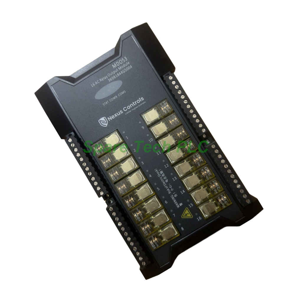
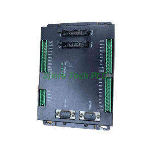
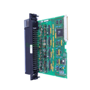
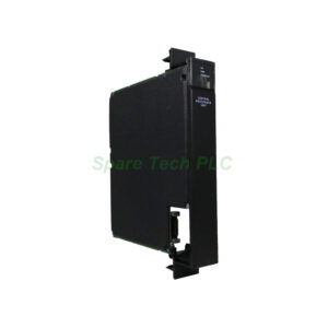
GE MDO53 Nexus Series Digital Output Module
Product Introduction
The GE MDO53 belongs to the Nexus series and functions as a high-density relay output module. This unit provides 16 normally-open relay channels, each rated for 12A@250V AC resistive loads. The compact design measures 49cm × 14cm × 2.7cm and weighs only 0.4kg. Each output includes a dedicated LED for instant status verification. Additionally, the MDO53 delivers exceptional isolation—3000VAC between channels and the system bus—making it suitable for driving contactors, motor starters, solenoid valves, and alarm horns in power generation and industrial process environments.
Technical Specifications
Output Characteristics
The module offers 16 independent relay outputs, each rated for substantial AC and DC loads. For resistive loads, the contact capacity reaches 12A at 250V AC and 12A at 30V DC. For inductive loads, the rating adjusts to 7.5A at 250V AC and 6A at 30V DC. These generous margins allow the GE MDO53 to directly control medium-power devices without external interposing relays. The output type is specified as 24V DC/100mA for the coil drive, ensuring compatibility with standard PLC output circuits.
Indication and Diagnostics
Every output channel features a dedicated green LED that illuminates when the relay coil is energised. This visual feedback simplifies commissioning and troubleshooting. Furthermore, the MDO53 includes three system-level LEDs: RUN indicates module health, COM shows serial bus activity, and FLT signals internal faults. Together, these indicators enable rapid fault localisation without specialised tools.
Isolation and Safety
Isolation ratings are exceptionally high. Channel-to-channel isolation reaches 1000VAC, preventing cross-talk between different field circuits. Channel-to-ground isolation stands at 2500VAC, while the system bus isolation achieves 3000VAC. This triple isolation layer protects the host controller from destructive surges and transients. Therefore, the MDO53 works safely in high-voltage switchgear and motor control centres.
Communication and Bus
The module connects to the Nexus backplane via a redundant high-speed intelligent serial bus at 1Mbps. A female DB-9 connector serves as the physical interface. This redundant bus topology ensures continuous operation even during single-path failures. Meanwhile, the embedded 32-bit processor manages output state updates with deterministic timing.
Power Consumption
Typical power draw is a modest 1.3W when all relays are de-energised. At maximum load with all 16 relays active, consumption rises to 11W. The GE MDO53 accepts a single 24V DC supply (21.6–26.4V range), which powers both the logic circuits and relay coils.
Mechanical and Environmental Parameters
Physical Dimensions
The module measures 490mm in width, 140mm in height, and 27mm in depth. This slim profile allows high-density mounting in Nexus series racks.
Terminal Connections
A single-row European-style removable terminal block accepts 2.5mm² wire, supporting dual-wire terminations. Each output terminal provides both the relay common (C) and normally-open (NO) contact. The detachable design accelerates field wiring and module exchange.
Environmental Limits
Operating temperature ranges from 0°C to 60°C, with relative humidity between 10% and 90% (non-condensing). Vibration resistance covers 10–500Hz at acceleration not exceeding 10m/s². Industrial dust tolerance follows the same standard: particles larger than 0.5µm limited to fewer than 18,000 per litre.
Regulatory Compliance
The MDO53 complies with CFR 47 FCC Part 15: 2009, ANSI C63.4-2003, EN 61326-1: 2006, CISPR 11: 2007, and IEC 61000-4-2/3/4/5/6/8/11. It carries CE certification as part of the complete GE Nexus system.
Installation Guidance
Mounting Instructions
Secure the GE MDO53 to the rack using the provided screw kit. Align the backplane connectors carefully before seating the module. Tighten screws progressively to avoid warping the PCB.
Wiring Recommendations
Use 2.5mm² stranded copper wire for load connections. Strip 7–8mm of insulation and insert into the removable terminal block. For AC loads, connect the live wire to the NO terminal and the load to the common terminal. For DC loads, observe polarity if the load includes freewheeling diodes. The MDO53 does not provide internal snubbers, so external RC suppression may be required for highly inductive loads.
Load Protection
Although the relay contacts are robust, inductive loads can generate voltage spikes. GE recommends using external varistors or RC snubbers across the load terminals to prolong contact life. This practice reduces arcing and maintains the rated electrical endurance of the MDO53 relays.
Bus and Power Connection
Connect the DB-9 port to the system bus using a shielded serial cable. Apply 24V DC power to the designated input terminals. The module draws maximum current during simultaneous relay energisation, so size the power supply accordingly.
Packaging List
GE MDO53 digital output module × 1
Removable terminal block (single-row, European-style) × 1
Screw mounting kit (screws and washers) × 1 set
Product label with serial number × 1
Quick installation guide (printed) × 1
Shipping Method: FedEx, UPS, DHL
Frequently Asked Questions
Q1: Can the MDO53 switch DC loads with the same rating as AC loads?
No. The DC rating is lower due to arc extinction challenges. For resistive DC, the GE MDO53 supports 12A@30V DC. For inductive DC, the rating drops to 6A@30V DC. Always derate for DC applications.
Q2: Are the relay contacts mechanically or electrically isolated from each other?
Yes. Each relay is fully isolated from adjacent channels with 1000VAC dielectric strength. This allows the MDO53 to switch different voltage potentials on different channels without concern.
Q3: What is the expected electrical life of the relays?
The MDO53 relays are rated for 100,000 operations at full resistive load. With inductive loads or frequent switching, the contact life reduces. Using external arc suppression extends longevity significantly.
Q4: Does the module support pulse-width modulation (PWM) or high-speed cycling?
No. The GE MDO53 uses mechanical relays with typical operate and release times of approximately 10ms. For high-speed switching applications, consider solid-state output modules instead.
Q5: What happens if an output relay welds closed due to an overload?
The MDO53 has no built-in weld detection. However, the channel LED will remain lit regardless of the commanded state. In this case, you can detect the fault by comparing the LED status with the output command from the host controller.