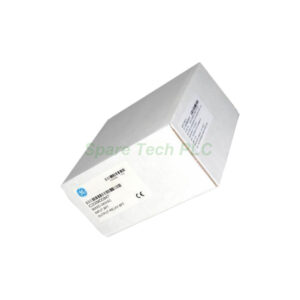
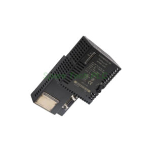
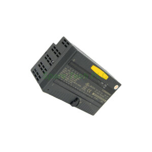
IS200TTURH1BEC GE Mark VI Turbine Board
Product Introduction
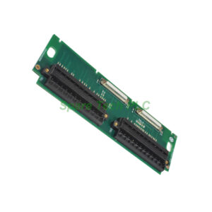
The IS200TTURH1BEC acts as a critical interface within the turbine I/O processor. GE designed this board for the Mark VI control system. It handles speed sensing, voltage monitoring, and breaker control. You can use it in both simplex and triple modular redundancy (TMR) configurations.
Technical Specifications
Speed Measurement Inputs
This board includes 12 passive pulse rate devices. They sense the turbine’s toothed wheel. Each device generates electrical pulses as the wheel rotates. This setup ensures accurate speed measurement. Additionally, it provides built-in redundancy for critical speed data.
Voltage Signal Monitoring
The IS200TTURH1BEC actively monitors generator voltage. It also checks bus voltage levels. Both signals come from potential transformers. These transformers step down high voltages to measurable levels. Constant monitoring helps detect deviations. The system can then trigger alerts or corrective actions.
Output and Relay Features
125V dc output for the main breaker coil. This supports automatic generator synchronization.
Three relays: K25, K25P, and K25A. All three must close to supply 125V dc power. This action closes the main breaker 52G.
Shaft voltage and current sensor inputs. These help measure induced shaft parameters.
Signal Connectivity
The speed signal cable connects through the JR5 connector. Other signals use the JR1 connector. For TMR systems, signals distribute across JR5, JS5, JT5, JR1, JS1, and JT1. This setup ensures failover capabilities.
Jumper Configuration
Jumpers JP1 and JP2 select between SMX and TMR options. They control relay drivers K25 and K25P. Therefore, you can easily match the board to your system’s redundancy level.
Mechanical and Environmental Parameters
Dimensions: 10.16 cm wide x 33.02 cm high
Temperature Range: -30 to 65°C
Technology: Surface-mount
Country of Manufacture: USA
Installation Guide
First, gather all necessary components. These include magnetic pickups, shaft pickups, potential transformers, and breaker relays.
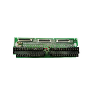
Next, locate terminal blocks TB1 and TB2. Each block has 24 terminals. They accept wires up to 12 AWG. Secure each block with two screws. A shield termination strip sits next to each block. Connect this strip to chassis ground for proper shielding.
Then, set jumpers JP1 and JP2 according to your system type. Use SMX for simplex or TMR for triple modular redundancy.
For optional TTL connections, use terminal block TB3. Note that active speed pickups may need an external power supply.
After wiring, connect cable connectors. Simplex systems use JR5 and JR1. TMR systems use all six connectors: JR5, JS5, JT5, JR1, JS1, and JT1.
Finally, perform thorough testing. Verify each input and output functions correctly. This step helps identify any wiring errors or configuration issues.
Packaging List
Frequently Asked Questions (FAQ)
1. Can I use the IS200TTURH1BEC in a simplex system?
Yes, the IS200TTURH1BEC works in simplex systems using JR5 and JR1 connectors. Set jumpers JP1 and JP2 to SMX.
2. What voltage does the main breaker output provide?
The board provides a 125V dc output for the main breaker coil. This supports automatic generator synchronization.
3. How many speed inputs does this board have?
It has 12 passive pulse rate devices. They sense the toothed wheel for accurate turbine speed measurement.
4. What shipping methods are available?
We ship via FedEx, UPS, and DHL. All items are packed securely to prevent damage.
5. Does this board support TMR systems?
Yes, for TMR systems use all six connectors: JR5, JS5, JT5, JR1, JS1, and JT1. The board supports ⅔ logic voting.