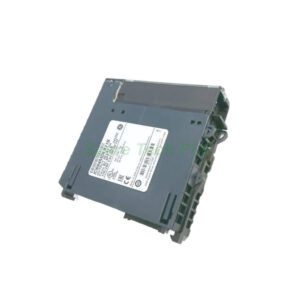
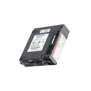
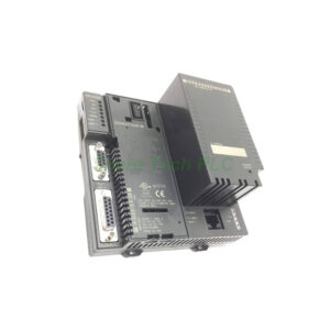
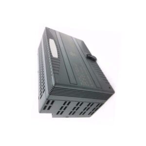
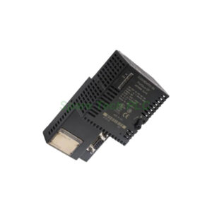
IC694MDL752 GE Fanuc High-Density Output Module
Product Introduction
The IC694MDL752 is a versatile high-density discrete output module from GE Fanuc, designed for the RX3i PACSystem platform. This module provides 32 digital output channels arranged in four isolated groups of eight channels each. It supports two operating modes: TTL mode at 5 VDC and 12/24 VDC mode, offering exceptional flexibility for mixed-voltage control applications.
Additionally, the IC694MDL752 features negative-logic sinking outputs, making it suitable for driving various loads such as solenoids, indicators, and solid-state relays. The module mounts in any available I/O slot of the RX3i backplane and can function as either a local output module or a distributed output module at a remote I/O station. Its compact single-slot design maximizes rack space utilization.
Operating Modes and Voltage Ranges
The IC694MDL752 offers two distinct operating modes to accommodate different field devices. In TTL mode, the module operates at 5 VDC with an output voltage range of 4.75 to 5.25 VDC. This mode is ideal for driving electronic loads and TTL-compatible circuits. Each output point sinks up to 25 mA in this configuration, providing reliable signal-level switching.
In the 12/24 VDC mode, the IC694MDL752 handles loads from 10.2 to 28.8 VDC. This broader range covers both 12-volt and 24-volt industrial devices, including relays, pilot lights, and small actuators. Each output point sinks up to 0.5 amps in this mode, delivering substantial power for field devices. Furthermore, you can mix different load types across groups because each group has its own common terminal.
Output Configuration and Group Isolation
The IC694MDL752 features 32 output points divided into four groups, with each group containing eight channels. Each group has a dedicated common terminal, providing point-to-point isolation between groups. This design allows you to power different voltage levels on different groups simultaneously. For instance, you can drive TTL loads on group 1, 12 VDC loads on group 2, and 24 VDC loads on group 3 without interference.
Moreover, each group supports a maximum load of 3.0 amps, while the common pin handles up to 4.0 amps. The module's negative-logic configuration means outputs sink current to ground when activated, which is common in many industrial control systems. The internal pull-up resistors on each output ensure defined states during power-up or fault conditions.
Current Ratings and Power Consumption
The IC694MDL752 delivers robust output current capacity across its operating modes. In TTL mode, each point provides 25 mA, while in 12/24 VDC mode, each point supplies 0.5 amps. The module draws a maximum of 260 mA from the 5-volt backplane bus, calculated as 13 mA base current plus 3 mA per active output and 4.7 mA per illuminated LED.
Additionally, the user-supplied power per group varies with voltage. At 5 VDC, each group draws 12 mA maximum when all eight outputs are ON. At 12 VDC, this increases to 25 mA per group, and at 24 VDC, it reaches 44 mA per group. Therefore, you should calculate your total power requirements carefully to avoid exceeding your external power supply capacity.
Response Time and Inrush Protection
The IC694MDL752 delivers fast switching performance with a maximum on/off response time of just 0.5 milliseconds. This speed makes it suitable for high-speed applications such as positioning systems, high-speed counting, and rapid sequencing processes. The module's fast response ensures precise control of time-critical operations.
For protection, the module offers an inrush rating of 4.6 amps for 10 milliseconds. This rating accommodates the initial surge current typically seen when switching capacitive or incandescent loads. The internal protection circuitry prevents damage from transient overcurrent conditions, enhancing module reliability in demanding industrial environments.
LED Indicators and Status Monitoring
The IC694MDL752 features 32 individually numbered LEDs on the front panel, providing clear visual status for each output point. These LEDs indicate whether each channel is ON or OFF, enabling quick diagnostics without external tools. This feature significantly reduces troubleshooting time during commissioning and maintenance.
Furthermore, the module's LED array helps technicians verify correct wiring and logical operation. Each LED corresponds to a specific output point, allowing immediate identification of faulty channels. The bright indicators remain visible even in dimly lit control cabinets, improving operational convenience.
Connectors and Wiring Options
The IC694MDL752 is equipped with two embedded compact module connectors designed for compatibility with male 24-pin Fujitsu FCN-365P024-AU connectors. This standardized interface simplifies field wiring and ensures reliable connections. You can either assemble custom cables or use pre-wired cables with catalog numbers IC694CBL327 and IC694CBL328.
For custom installations, the terminal assignments follow a clear layout that facilitates quick wiring. Each group's eight outputs are clearly labeled, and the common terminals are easily accessible. When using pre-wired cables, the IC694CBL327 and IC694CBL328 options provide ready-to-use connectivity, reducing installation time and minimizing wiring errors.
Installation Guidelines
The IC694MDL752 installs in any available I/O slot of the RX3i backplane. It supports both local installation at the CPU rack and distributed installation at remote I/O stations. However, please note that this module does not support hot-swapping, so you must power down the system before installing or removing it.
To install, first select an empty slot on the backplane. Then slide the IC694MDL752 into the slot until it seats firmly against the backplane connector. Secure the module with the retaining screws to ensure mechanical stability. Finally, connect your field wiring to the appropriate terminals using either custom cables or the recommended pre-wired options.
System Integration and Compatibility
The IC694MDL752 is compatible with RX3i CPUs and works seamlessly with other RX3i modules. The number of module instances depends on available slots and the I/O capacity of the host processor. For system planning, remember that this high-density module consumes only 260 mA from the 5V backplane bus, minimizing load on the system power supply.
Additionally, the module supports the same programming and configuration tools as the rest of the RX3i product family. You can easily integrate it into existing Proficy Machine Edition projects. Its negative-logic design aligns with many legacy systems, making it an excellent choice for both new installations and system upgrades.
Packaging and Shipping
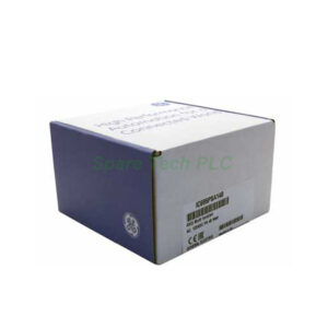
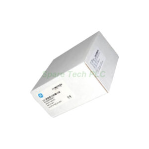
Each IC694MDL752 unit ships in an anti-static protective package to prevent electrostatic discharge damage. The box contains the output module, a connector guide, and a quick-start installation reference. All orders are dispatched via reliable carriers, including FedEx, UPS, and DHL, with real-time tracking available for every shipment.
Frequently Asked Questions
1. Can I mix TTL and 12/24V loads on the same module?
Yes, the IC694MDL752 allows different groups to operate at different voltages. Each group has its own common terminal, so you can mix load types across groups.
2. What is the maximum current per output point?
The IC694MDL752 provides 25 mA per point in TTL mode and 0.5 amps per point in 12/24 VDC mode.
3. Does this module support hot-swapping?
No, the IC694MDL752 does not support hot-swapping. You must power down the system before installing or removing the module.
4. What pre-wired cables work with this module?
The IC694MDL752 is compatible with pre-wired cables IC694CBL327 and IC694CBL328. You can also assemble custom cables using Fujitsu FCN-365P024-AU connectors.
5. How do I know which outputs are active?
The IC694MDL752 features 32 individually numbered LEDs on the front panel, showing the status of each output point clearly.