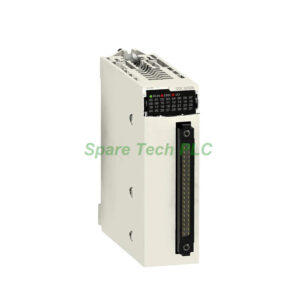
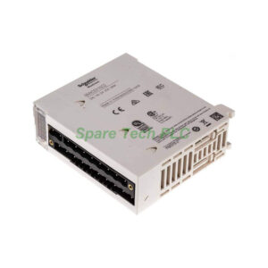
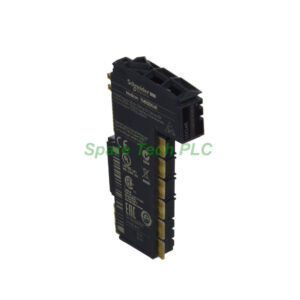
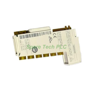
STBACI1400K – Complete 8-Channel Analog Input Kit for STB Systems
What You Get in This Kit
The STBACI1400K simplifies ordering by bundling everything you need. Instead of sourcing separate components, this kit delivers a complete analog input solution. Inside the box, you will find:
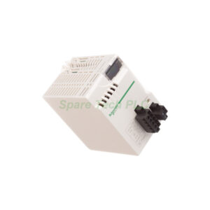
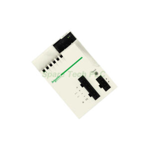
STBACI1400 analog input module
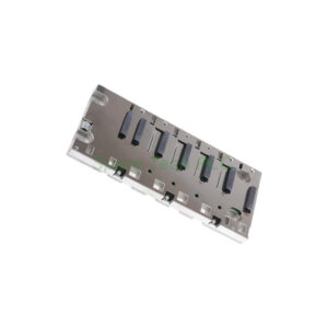
STBXBA2000 mounting base
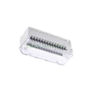
STBXTS1100 6-terminal screw type connector
STBXTS2100 6-terminal spring clamp connector
This all-in-one approach saves procurement time and ensures component compatibility. The STBACI1400K works perfectly with Modicon STB distributed I/O networks.
Key Technical Specifications
Analog input type: current (0-20mA or 4-20mA).
Number of inputs: 8 channels.
Resolution: 15 bits plus sign.
Filter type: single low pass input filter at 985 Hz.
Update time: 22 ms for all channels.
Absolute maximum input: 25mA / 50V DC.
Input impedance: ≤250 Ohm.
Additionally, the STBACI1400K provides 100mA maximum supply current per input channel for loop-powered sensors. This feature eliminates the need for external power supplies on many 2-wire transmitters.
Accuracy and Linearity
Integral linearity: ±0.08% of full scale.
Differential linearity: monotonic (no missing codes).
Absolute accuracy error: ±0.4% of full scale.
Temperature drift: ±0.005% per °C.
These accuracy figures make the STBACI1400K suitable for process monitoring and control applications. Temperature drift remains very low, so readings stay stable across varying plant floor conditions.
Power and Current Consumption
Rated supply voltage: 24V DC (from power distribution module).
Logic bus current consumption: 90mA at 5V DC.
Compatible power modules: STBPDT3100 or STBPDT3105.
The STBACI1400K draws power from the STB island's logic bus. You must use a compatible power distribution module to supply the 5V DC logic power.
Isolation and Protection
Channels to logic bus insulation: 1500V for 1 minute.
Channels to sensor bus insulation: 30V.
Overvoltage category: II.
Furthermore, the STBACI1400K supports both cold swapping and hot swapping. For hot swapping, you need a standard Network Interface Module (NIM). The fallback state is user configurable with standard NIMs or fixed to state 0 with basic NIMs.
Mechanical Dimensions
Width: 128.3 mm.
Height: 18.4 mm.
Depth: 70 mm.
This compact form factor fits neatly into STB islands. The STBACI1400K mounts onto the STBXBA2000 base, which then clips onto a DIN rail.
Environmental Ratings
Operating temperature: -25…70°C (-13…158°F).
Storage temperature: -40…85°C (-40…185°F), no derating.
Relative humidity: 95% at 60°C, non-condensing.
IP rating: IP20 (EN 61131-2 class 1).
Operating altitude: ≤2000m.
Pollution degree: 2 (IEC 60664-1).
Vibration resistance (DIN rail 35x7.5mm):
±0.35mm at 10…58 Hz
3gn at 58…150 Hz
Vibration resistance (DIN rail 35x15mm):
Shock resistance: 30gn for 11 ms (IEC 88-2-27).
Certifications and Standards
The STBACI1400K carries multiple certifications:
These certifications allow installation in hazardous locations and various global markets.
Installation Guidelines
First, clip the STBXBA2000 base onto a standard DIN rail. Next, snap the STBACI1400 module onto the base. Then, connect either the screw terminal block (STBXTS1100) or spring clamp block (STBXTS2100) to the module's front. Finally, wire your 4-20mA or 0-20mA sensors to the appropriate terminals.
For loop-powered 2-wire transmitters, use the sensor supply output from each channel. For externally powered 4-wire transmitters, connect the signal wires only. Always terminate the bus correctly at both ends of the STB island.
Data Format and Addressing
Data format standards: EN 61131-2 and IEC 61131-2.
Addressing requirement: 16 input words.
Each of the 8 analog inputs consumes 2 input words. The first word contains the analog value (15 bits plus sign). The second word typically provides diagnostic or status information.
Compatibility Requirements
The STBACI1400K requires:
A power distribution module (STBPDT3100 or STBPDT3105) for logic power
A Network Interface Module (NIM) for communication to the fieldbus
STB bus terminators at both ends of the island
This kit works with all Modicon STB NIMs supporting analog I/O, including CANopen, Modbus, and EtherNet/IP versions.
Packaging List
STBACI1400 analog input module (1 unit)
STBXBA2000 mounting base (1 unit)
STBXTS1100 6-terminal screw connector (1 unit)
STBXTS2100 6-terminal spring clamp connector (1 unit)
Bus terminator cover (installed on base)
Note: No certificates or warranty documents are included. Power distribution module and NIM sold separately.
Shipping & Delivery
All orders ship via FedEx, UPS, or DHL with full tracking. Anti-static packaging protects sensitive analog components.
Frequently Asked Questions (FAQ)
1. Can the STBACI1400K accept both 4-20mA and 0-20mA signals?
Yes. The module supports both ranges. Configure the range through your STB configuration software. The 15-bit plus sign resolution works for either range.
2. Do I need an external power supply for 2-wire transmitters?
No. The STBACI1400K provides 100mA of loop power per channel. This built-in supply powers most standard 2-wire 4-20mA transmitters directly.
3. What is the difference between screw and spring connectors?
The STBXTS1100 uses screw terminals for permanent installations where vibration is low. The STBXTS2100 uses spring clamps for faster wiring and better vibration resistance. Both are included, so you can choose.
4. How many STBACI1400K modules can I put in one STB island?
The maximum number depends on your NIM and power budget. Each STBACI1400K consumes 90mA from the 5V logic bus. Consult your power distribution module's capacity.
5. What does "15 bits + sign" mean for the resolution?
The module provides 15 bits of magnitude data (0 to 32767) plus one sign bit. For 4-20mA, the reading is always positive. For 0-20mA, negative values indicate reversed polarity or configuration errors.