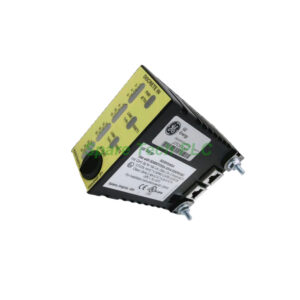
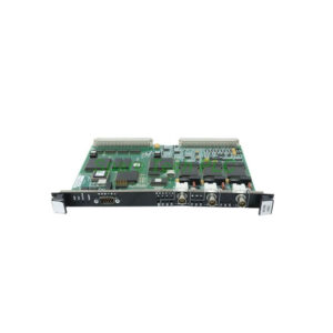
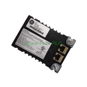
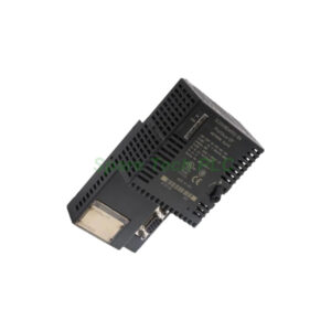
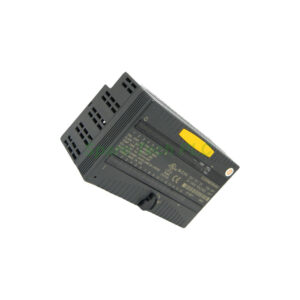
GE IS220PAICH1B Analog I/O Pack for Mark VIe Systems
Product Introduction
The IS220PAICH1B belongs to GE's Mark VIe distributed I/O platform. This analog I/O pack connects one or two I/O Ethernet networks to an analog input terminal board. Inside, you will find a shared processor board and a dedicated acquisition board for analog functions. The pack supports ten inputs and two outputs with a fast 5 ms scan time. Additionally, auto-reconfiguration allows quick replacement without manual setup.
Technical Specifications of the IS220PAICH1B
Part Number: IS220PAICH1B
Manufacturer: General Electric (USA)
Series: Mark VIe
Product Type: Analog I/O Pack
Channel Configuration: The pack handles 12 channels per terminal board, consisting of 10 analog inputs and 2 analog outputs.
Analog Input Specifications (Channels 1-8): These eight inputs support multiple configurations. You can set them for 1-5 V dc, ±5 V dc, ±10 V dc, or 0-20 mA current loop. The terminal board contains load resistors for current inputs, and the IS220PAICH1B senses voltage across these resistors.
Analog Input Specifications (Channels 9-10): The last two inputs accept 0-20 mA or ±1 mA current signals. This flexibility suits low-current sensors like certain gas detectors or thermocouple transmitters.
Analog Output Specifications: The pack features two 0-20 mA current loop outputs. They operate at 18 V compliance in simplex or TMR mode. A 14-bit DAC sends a current reference to the regulator loop.
Resolution & Scan Time: Input converter resolution is 16-bit using an analog-to-digital converter. Normal scan time runs at 5 ms (200 Hz). Note that the maximum controller frame rate is 100 Hz.
Power Consumption: Typical consumption is 5.3 W, with worst case at 6.2 W. Analog transmitter power is 22.8 VDC.
Environmental Ratings: Ambient temperature range spans -40°F to 158°F (-40°C to 70°C).
Certifications: The IS220PAICH1B holds ATEX Zone 2, Group IIC certification (EN 60079-11:2012; EN 60079-7:2015; EN 60079-0:2018). Non-hazardous certification is UL E207685.
Functional Description and Processor Features
The IS220PAICH1B contains a processor board linked to a dedicated acquisition board. When input power is applied, a soft-start circuit gradually increases voltage on the processor board. Local power supplies turn on in sequence, and the processor reset remains disabled.
After finishing self-test routines, the processor loads application code from flash memory. This code is specific to the analog I/O function. It reads board ID information to verify that the application code, acquisition board, and terminal board are all correctly matched. This verification prevents configuration errors.
Auto-Reconfiguration Feature
The auto-reconfiguration feature significantly simplifies maintenance. When the controller detects an IS220PAICH1B booting with a different configuration, and auto-reconfiguration is enabled, a reconfiguration file downloads automatically from the controller to the I/O pack.
The bootload, baseload, firmware, and parameters all get reconfigured during this process. Unless the pack already has the latest version, it gets updated with the current configuration that matches the controller's settings. You can replace a failed IS220PAICH1B without any manual configuration steps.
Analog Input Hardware Details
For all ten input channels, the IS220PAICH1B accepts voltage signals from the terminal board. The analog input section consists of an analog multiplexer block, several gain and scaling options, and a 16-bit analog-to-digital converter.
Depending on your configuration, inputs 1 through 8 work as 5V or 10V scale signals. When configured for current inputs, the terminal board includes a 250Ω burden resistor. This resistor produces a 5V signal at 20 mA, which the pack then reads.
Analog Output Hardware and Suicide Relay
The IS220PAICH1B has two 0-20 mA analog outputs. Each output circuit includes a normally open mechanical relay for enabling or disabling output operation. This relay serves a critical role in TMR systems.
In a TMR configuration, the relay removes a failed output. The remaining two IS220PAICH1B packs then create the correct output without interference from the failed circuit. When the suicide relay deactivates, the output opens through the relay. This action short-circuits the analog output from the terminal board's customer load, effectively isolating the failed channel.
Compatible Terminal Boards
The IS220PAICH1B works with several IS200 series terminal boards:
These terminal boards contain the burden resistors for current loop inputs. Always use the correct terminal board for your application.
Diagnostic Alarms and Troubleshooting
The IS220PAICH1B generates specific alarms to help with maintenance. Pay attention to these common alarms:
Alarm 66-67: Indicates individual output current is too high relative to total current. Check your field wiring and connected load.
Alarm 82-83: Indicates the suicide relay is non-functional. Possible causes include a mismatch between the suicide relay command and associated feedback, hardware failure, or a relay failure on the acquisition board. The main solution for this alarm is replacing the IS220PAICH1B pack itself.
Before performing any tests, verify there are no diagnostic faults on the pack under test. Any expected diagnostic faults should be documented in your acceptance criteria.
Compressor Stall Detection
The IS220PAICH1B includes compressor stall detection functionality. Detection and relay operation occur within 30 seconds. This feature protects rotating equipment from damaging surge conditions.
Installation and Mounting Guide
Follow these steps to install the IS220PAICH1B correctly:
First, power down the entire rack system. Next, mount your compatible terminal board (IS200TBAIH1C, IS200TAIH1A, or IS200TAIH2A) onto the DIN rail or backplane. Then, slide the IS220PAICH1B pack onto the terminal board. The DC-37 pin connector on the pack mates directly with the terminal board connector.
Connect power via the three-pin power input. Use the two RJ45 Ethernet connectors for IONet communication. Finally, verify that all LED indicators show normal operation.
For best results, use shielded cables for all analog signals. Ground the shield only at the panel end to avoid ground loops.
Why Choose This Mark VIe Analog I/O Pack?
First, the IS220PAICH1B offers 12 channels in a compact form factor. Second, auto-reconfiguration reduces maintenance time and eliminates configuration errors. Third, the suicide relay design supports TMR applications safely. Finally, GE's Mark VIe platform is widely used in power generation and industrial turbomachinery.
Packaging List
1 x IS220PAICH1B Analog I/O Pack
1 x Anti-static protective bag
1 x Quick installation reference card
Note: Terminal boards, Ethernet cables, power cables, certificates, and warranty documents are not included.
Shipping Information
All orders ship via global express carriers. Your IS220PAICH1B will be sent using FedEx, UPS, or DHL. Most in-stock orders leave our warehouse within 24 hours. You will receive a tracking number by email.
Frequently Asked Questions (FAQ)
1. Is the IS220PAICH1B backward compatible with the IS220PAICH1A?
Yes, the IS220PAICH1B is the second version of the PAIC unit. However, it operates on a different minimum voltage (22.5V) compared to the earlier version. Check your system's power supply before replacing an older unit.
2. Can I use the IS220PAICH1B in a TMR configuration?
Yes, the IS220PAICH1B supports TMR operation. The suicide relay on each pack allows removal of a failed output. The remaining two packs continue to produce the correct output without interference.
3. What happens if the auto-reconfiguration feature is disabled?
If auto-reconfiguration is disabled, the IS220PAICH1B will not update automatically. You must manually configure each replacement pack using ToolboxST. GE recommends keeping this feature enabled for easier maintenance.
4. How do I configure inputs 1-8 for 0-20 mA current mode?
You configure the input type using GE's ToolboxST software. When set to current mode, the terminal board's 250Ω burden resistor creates a 5V signal at 20 mA. The IS220PAICH1B then reads this voltage and scales it to the current value.
5. What is the maximum cable length for analog inputs on the IS220PAICH1B?
Keep analog input cables under 300 meters (985 feet) for voltage signals. For current loop (0-20 mA) mode, you can extend up to 600 meters (1968 feet) due to better noise immunity. Always use twisted-pair shielded cable for best results with the IS220PAICH1B.