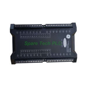
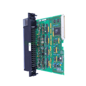
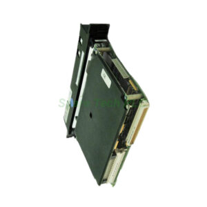
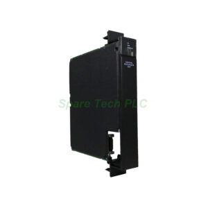
369B1871G0007 GE Nexus Analog Output Board
Product Introduction
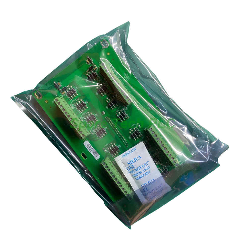
The GE 369B1871G0007 functions as an analog output terminal board within the GE Nexus series. This module translates digital PLC or DCS commands into continuous analog signals for field devices like servo valves and variable frequency drives. It works seamlessly with GE XDPS-400 and OC6000E distributed control systems. The 369B1871G0007 features a configuration environment that includes both development mode and run mode. This dual-mode design gives engineers full control over system setup and real-time operation.
Configuration Software Overview
The configuration software for the GE 369B1871G0007 typically comes in multiple versions based on I/O or variable point counts. Even within the same brand, you will find different editions tailored to project scale. The software operates in two primary modes: development mode and run mode. In development mode, engineers build the operator interface from scratch. In run mode, the system executes the configured logic and displays live process data. This flexible architecture makes the 369B1871G0007 suitable for both small-scale pilot plants and large industrial facilities.
Development Mode Functions
In development mode, the GE 369B1871G0007 allows you to create comprehensive graphical displays. You can design process overview screens, detailed loop panels, and alarm summaries based on field requirements. Additionally, you select the communication protocol that matches your downstream equipment. Common choices include Modbus, Profibus, and proprietary GE protocols. After protocol selection, you establish variable-to-device connections that link on-screen elements to actual I/O channels. The 369B1871G0007 supports a wide range of signal types, making it highly adaptable. Furthermore, the development environment includes debugging tools that let you test each channel before going live.
Run Mode Operation
Once the configuration is complete, the GE 369B1871G0007 operates in run mode. In this state, the terminal board communicates actively with the field devices. It receives digital setpoints from the controller and converts them into precise analog outputs. The operator interface displays dynamic process data through animated graphics, trend charts, and numeric indicators. For instance, you can watch valve positions change in real time as the 369B1871G0007 responds to control loop calculations. The board also transmits field-collected data back to the host system, ensuring full visibility of process conditions.
Data Logging and Reporting
The GE 369B1871G0007 works with configuration software that handles extensive post-processing tasks. The system can store historical data directly into databases for long-term analysis. Moreover, it generates customizable reports that summarize production performance, alarm events, and equipment status. You can schedule automatic report generation at shift changes or end-of-day cycles. The 369B1871G0007 also supports print functions, allowing operators to produce hard copies of critical process information. This data management capability transforms raw I/O signals into actionable business intelligence.
Application Scenarios
The GE 369B1871G0007 serves primarily in GE XDPS-400 and OC6000E DCS environments. Typical applications include:
Power plant turbine control systems
Chemical reactor temperature and flow regulation
Metallurgical furnace atmosphere control
Water treatment chemical dosing systems
Pulp and paper mill process loops
The 369B1871G0007 adapts to any situation requiring high-precision analog control with advanced visualization.
Installation Guidelines
Before installing the GE 369B1871G0007, verify that your configuration software version supports the required point count. Check the communication protocol compatibility with your downstream devices. To install:
De-energize the system chassis before handling the board.
Insert the 369B1871G0007 into an available slot on the backplane.
Secure the board using the integrated mounting hardware.
Connect field wiring to the terminal blocks as per the silkscreen labels.
Power up the system and launch the configuration software.
Configure the board parameters in development mode before switching to run mode.
Packaging List
1 x GE 369B1871G0007 Analog Output Terminal Board
1 x backplane interface cable
1 x terminal block connector set
1 x configuration software quick-reference card
Note: Shipping is handled via FedEx, UPS, or DHL, depending on your regional service availability.
Frequently Asked Questions (FAQ)
Q1: What DCS platforms work with the 369B1871G0007?
A1: The GE 369B1871G0007 is specifically designed for GE XDPS-400 and OC6000E distributed control systems.
Q2: What is the difference between development and run modes?
A2: Development mode lets you build operator interfaces, set communication protocols, and link variables to channels. Run mode executes the configured logic and displays live process data.
Q3: How does the 369B1871G0007 handle data logging?
A3: The configuration software stores historical data in databases and generates customizable reports. It also supports scheduled printing for shift summaries.
Q4: Can I use this board with non-GE protocols?
A4: Yes, the 369B1871G0007 supports multiple communication protocols including Modbus and Profibus, in addition to GE proprietary options.
Q5: What determines the software version I need?
A5: The software version depends on your I/O or variable point count. The 369B1871G0007 works with various editions of the same configuration software brand.