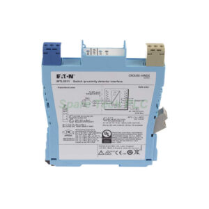
MTL5314 MTL Instruments Trip Amplifier 4-20mA
Product Introduction
The MTL5314 trip amplifier connects a 2- or 3-wire 4/20mA transmitter from a hazardous area to a safe-area control system. This device from MTL Instruments offers one input channel with two independently configurable alarm outputs. Each output uses a changeover relay. You can set each relay to trip when the input signal rises above or drops below a preset value. Additionally, the unit supplies power to the transmitter with more than 17V at 20mA. HART communications remain unaffected when looping the signal through terminals 1 and 3.
Key Technical Specifications
The MTL5314 accepts a hazardous-area input signal from 0 to 24mA (including over-range). Input resistance is only 25Ω maximum. Response time stays below 75ms. Trip-points adjust via multiturn potentiometers on top of the unit. The trip-point range spans 0.5 to 22mA with an effective resolution of 20μA. Trip-point drift with temperature is a maximum of 1.5μA/°C. Hysteresis falls between 1% and 1.7% of the trip-point range.
For the safe-area output, two relays provide changeover contacts. Each relay's contact rating is 250V ac, 2A (cosø >0.7) or 40V dc, 2A resistive load. Contact life expectancy reaches 3.3 x 10⁵ operations. The power supply voltage ranges from 20 to 35V dc. Maximum current consumption at 24V with a 20mA signal is 85mA. Power dissipation at 24V with a 20mA signal is 1.7W.
Safety and Hazardous Area Compliance
The MTL5314 locates field equipment in Zone 0, IIC, T4–T6 hazardous areas or Div 1, Group A hazardous locations. For terminals 2 to 1 and 3, the safety parameters are 28V, 300Ω, 93mA. Terminals 1 and 3 meet EN50020 clause 5.4 with parameters U ≤ 1.5V, I ≤ 0.1A, P ≤ 25mW. These terminals connect without further certification into an IS loop with open circuit voltage not exceeding 28V.
LED Indicators and Terminal Functions
Three LEDs provide clear status indication. The green LED lights when power connects to the module. Two yellow status LEDs (one per trip) illuminate when the corresponding relay is energised (not tripped). Terminal functions are as follows: terminal 1 for current input, terminal 2 for transmitter supply +ve, terminal 4 for common, terminals 7-9 for Trip B (NC, COM, NO), terminals 10-12 for Trip A (NC, COM, NO), terminal 13 for supply –ve, and terminal 14 for supply +ve.
Mechanical and Environmental Data
This trip amplifier mounts on a standard 35 mm DIN rail. Dimensions follow the MTL5300 series form factor. The unit operates in ambient temperatures from -20°C to 60°C. Storage temperatures range from -40°C to 80°C. Humidity tolerance is 5-95% relative humidity non-condensing.
Installation Guidelines
Mount the MTL5314 on a 35 mm DIN rail in a safe-area cabinet or suitable enclosure. Connect the 4-20mA transmitter to terminals 1, 2, and 3 as required for 2-wire or 3-wire configuration. Apply 20-35 Vdc power to terminals 13 (-) and 14 (+). Wire the relay outputs (Trip A and Trip B) to your alarm or shutdown system. Use the multiturn potentiometers on top to set each trip-point. For series connection with an MTL5541 repeater, loop the transmitter signal through terminals 1 and 3. HART communicators connect anywhere along the 4-20mA loop without interference.
Packaging List
1 x MTL5314 trip amplifier unit
2 x Multiturn potentiometers (pre-installed on top)
1 x DIN rail mounting clip (integral)
No terminal crimps or ferrules included
Note: Certificates and warranty are not included in the package.
Shipping
We ship worldwide via FedEx, UPS, or DHL.
Frequently Asked Questions (FAQ)
1. Can the MTL5314 work with a 3-wire transmitter?
Yes, the MTL5314 supports both 2-wire and 3-wire 4-20mA transmitters. Use terminal 2 for transmitter supply and terminal 1 for the return signal.
2. Does this device support HART communication?
Yes, looping the transmitter signal through terminals 1 and 3 does not affect HART communications. You can connect a HART modem anywhere on the loop.
3. How do I set the two trip-points independently?
Use the two multiturn potentiometers accessible on the top of the unit. Each potentiometer corresponds to one relay (Trip A and Trip B). Turn them to set any trip-point between 0.5 and 22mA.
4. What happens to the relays during a power loss?
When power is lost, both relays de-energise. This means they revert to their non-energised (alarm) state. Therefore, you must design your safety logic accordingly.
5. Can I connect the MTL5314 in series with an isolator?
Yes, you can connect it in series with an MTL5541 4/20mA repeater power supply or equivalent device. This provides two trip alarm outputs directly from the transmitter signal.