Product Introduction
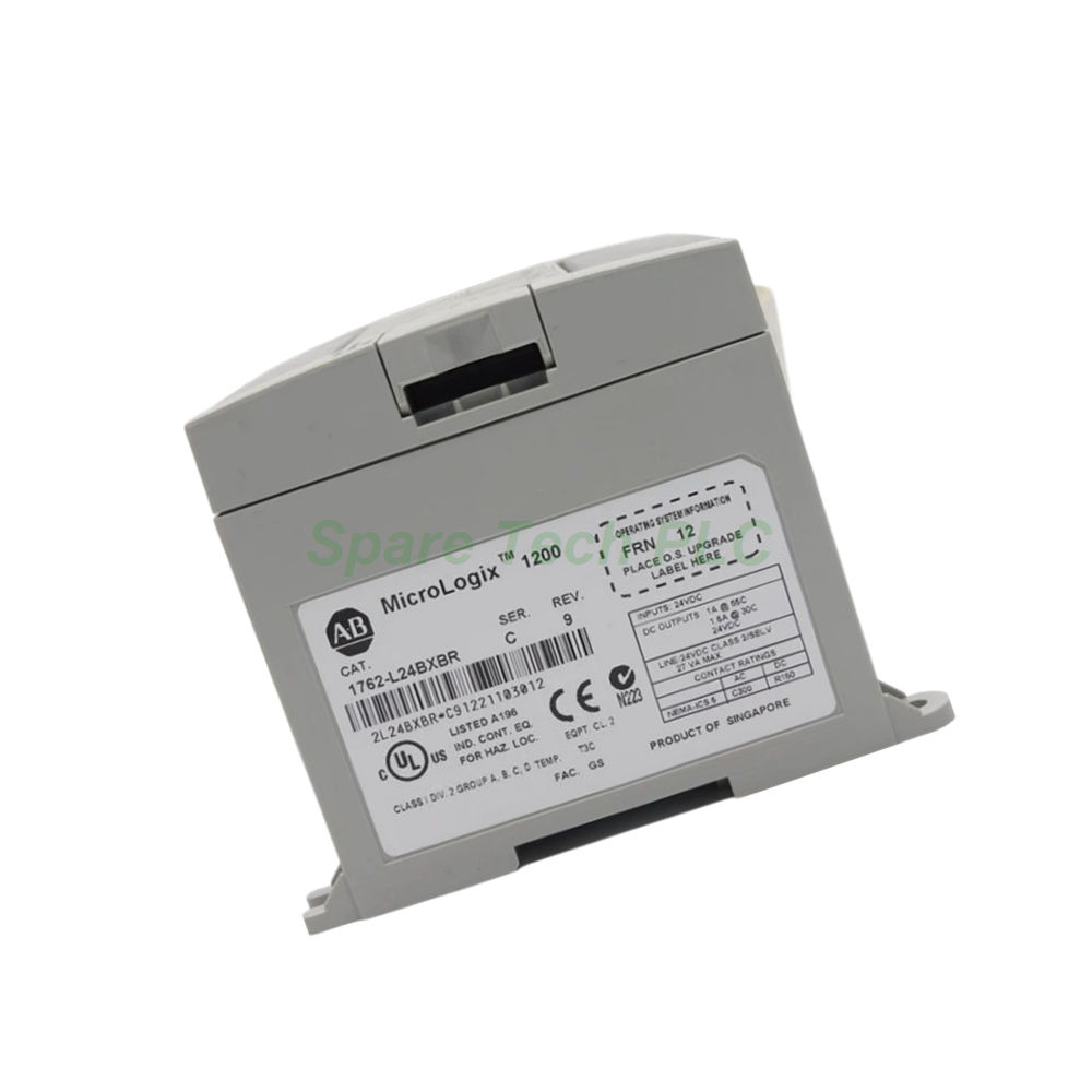
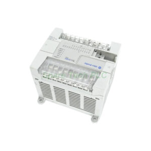
The Allen‑Bradley 1762‑L24BXBR programmable controller belongs to the MicroLogix 1200 series, a family known for reliable performance in light industrial environments. This 24‑point unit combines embedded I/O with expansion flexibility, letting you connect up to six 1762 expansion modules for additional digital or analog channels. Its dual communication ports and real‑time clock simplify system integration and scheduled control tasks. Whether you are upgrading an existing panel or building a new machine, the 1762‑L24BXBR delivers a balanced feature set at a competitive price point.
Technical Specifications
Power Supply
The controller operates on a 24VDC power source. Its power consumption reaches 82 VA, with an inrush current of 25A at 120VAC for 8 ms or 40A at 240VAC for 4 ms.
Input Channels
This unit provides ten standard 24VDC sink/source inputs alongside four fast 24VDC inputs. Specifically, input channels 0 through 3 accept signal frequencies from 0 to 20 kHz, while channels 4 and above handle 0 Hz to 1 kHz, depending on the scan time. Additionally, the 1762‑L24BXBR includes four pulse‑catch or latching inputs that capture and hold very brief signals for precise event tracking.
Output Channels
For outputs, the controller offers five relay outputs rated for 24‑125VDC or 120‑240VAC, with a minimum load current of 10A and a mechanical life of 20 million cycles. Furthermore, it includes four 24VDC FET outputs and one high‑speed 24VDC FET output, making it suitable for both standard and high‑speed switching applications.
Communication Interfaces
The 1762‑L24BXBR features two 8‑pin mini‑DIN serial ports. One port serves as a dedicated programming interface located on the side, while the primary port resides on the front panel for HMI or SCADA connectivity. Both ports support DF1, DH‑485, ASCII, and MODBUS protocols, enabling flexible integration with various devices. Consequently, you can perform online edits, uploads, downloads, and system commissioning with ease.
Additional Features
A built‑in real‑time clock allows scheduled control operations. Moreover, two trim potentiometers let you adjust internal registers or implement local manual control without external hardware.
Mechanical & Environmental Parameters
Dimensions and Mounting
The controller measures 160 mm in width, 90 mm in height (or 104 mm with the DIN latch open), and 87 mm in depth. Its compact footprint requires only 500 mm (2 inches) of clearance on all sides for proper ventilation and maintenance access. You can mount the 1762‑L24BXBR on a DIN rail or directly to a panel. Note that panel mounting offers less vibration resistance than DIN rail mounting, so choose the method that best suits your application environment.
Operating Conditions
The unit operates within an ambient temperature range of 0 to 55 degrees Celsius. With a shipping weight of just 2.4 pounds (1.1 kg), it remains lightweight and easy to handle during installation.
Expansion Capability
This controller supports up to six 1762 expansion I/O modules, which can be digital or analog types. As a result, you can scale the total I/O count to as many as 96 points, giving you ample room for future system growth.
Installation Guide
Step 1 – Mounting
First, choose between DIN rail or panel mounting. For DIN rail, simply snap the latch onto the rail until it clicks securely. For panel mounting, use appropriate screws through the mounting holes. Ensure the latch is fully closed before operation.
Step 2 – Wiring
Next, connect the 24VDC power supply to the designated terminals. Wire the input and output devices according to the terminal layout printed on the housing. For relay outputs, pay attention to the contact rating (24‑125VDC or 120‑240VAC) and ensure the load current meets the 10A minimum requirement.
Step 3 – Communication Setup
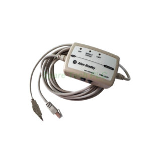
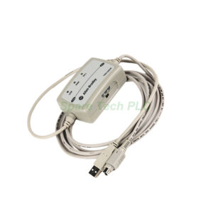
Then, attach your programming cable to either mini‑DIN port. Use the primary port for HMI connections and the side port for programming. Configure the protocol (DF1, DH‑485, ASCII, or MODBUS) in your software to match your network settings.
Step 4 – Power Up and Testing
Finally, apply 24VDC power and verify the status LEDs. Use the trim potentiometers to fine‑tune internal registers if needed. Perform a quick I/O check to confirm all channels respond correctly before deploying the system.
Packaging List
Allen‑Bradley 1762‑L24BXBR MicroLogix 1200 controller (1 unit)
DIN rail mounting latch (pre‑installed)
Terminal block connectors (plug‑in type, 1 set)
Quick start guide (printed)
Product information sheet
Note: Programming cables, software, and expansion modules are sold separately.
Shipping Information
All orders are shipped via FedEx, UPS, or DHL with tracking numbers provided upon dispatch. Standard packaging ensures safe transit, and expedited options are available upon request.
Frequently Asked Questions
Q1: What is the difference between the standard inputs and fast inputs on the 1762‑L24BXBR?
A: The fast inputs (channels 0–3) handle high‑speed signals up to 20 kHz, making them ideal for counting or positioning applications. Standard inputs (channels 4 and above) operate at up to 1 kHz, which depends on the controller's scan time.
Q2: Can I use the 1762‑L24BXBR with MODBUS devices?
A: Yes, absolutely. The primary communication port supports MODBUS protocol along with DF1, DH‑485, and ASCII, so you can easily connect to MODBUS‑compatible HMIs, drives, or sensors.
Q3: How many expansion modules can I add to this controller?
A: You can attach up to six 1762 expansion I/O modules, which can be a mix of digital and analog types. This expands your total I/O count to a maximum of 96 points.
Q4: What is the purpose of the two trim potentiometers?
A: These potentiometers let you adjust internal register values without programming software. You can use them for local manual control, speed trimming, or setpoint adjustments during commissioning.
Q5: Is the real‑time clock battery‑backed?
A: Yes, the built‑in RTC maintains time and scheduled tasks even during power outages, ensuring your control activities continue reliably after re‑powering.