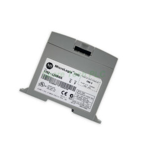
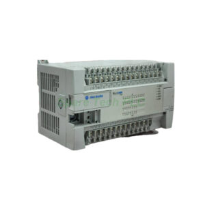
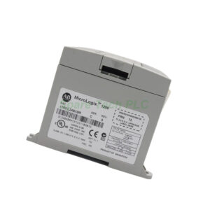
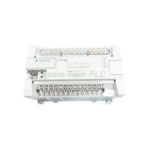
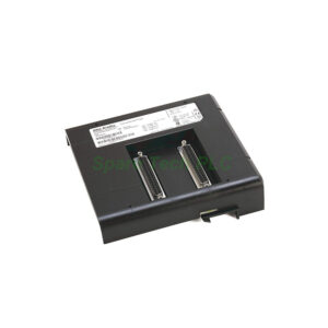
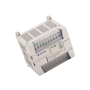
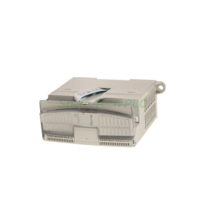
1762-L24BWAR MicroLogix 1200 Embedded I/O Controller
Product Introduction
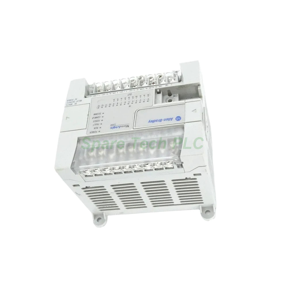
The 1762-L24BWAR from Allen‑Bradley is a self‑contained programmable logic controller within the MicroLogix 1200 family. This embedded I/O controller integrates a power supply, processor, and I/O into a single compact housing. Therefore, it simplifies system design and reduces panel space requirements.
This controller provides fourteen 24V DC digital inputs, which include ten standard inputs and four fast‑response inputs for high‑speed applications. These inputs support both sink and source wiring configurations, offering flexibility when connecting to various sensors, switches, and encoders. Additionally, the 1762-L24BWAR delivers ten relay outputs that can switch both AC and DC loads, making them suitable for driving contactors, solenoids, and indicator lamps.
Moreover, the built‑in RS232 communication port (Programmer/HMI Port) enables connection to programming terminals, HMIs, and other automation devices. However, note that this port operates in slave mode and supports only DH Full‑Duplex protocols; it cannot initiate messages, and its parameters are fixed. Furthermore, the controller operates on a wide AC supply range from 120 to 240V AC, accommodating global power standards.
The 1762-L24BWAR also features two onboard potentiometers for analog simulation, which is useful during testing and commissioning. Its compact dimensions and dual mounting options (DIN rail or panel) make it an excellent choice for control panels with limited space. Whether you are building a new machine or upgrading an existing system, this controller delivers dependable performance at an economical price.
Technical Specifications
The 1762-L24BWAR offers reliable performance across its I/O, communication, and power features. Key parameters are detailed below:
Power Supply
Nominal input voltage: 120/240V AC (operating range 120–240V AC)
Operating frequency: 47–63 Hz
Sensor supply: Internal COM connected to chassis ground (for input devices only)
Input Specifications (14 DC Inputs)
Input Current Details:
Off‑state voltage: 0–5V DC
Off‑state leakage: 1.5 mA maximum
Frequency response:
Total sensor current: Sum of all connected device currents
Output Specifications (10 Relay Outputs)
Contact configuration: Normally open (Form A)
Contact voltage range: 24–125V DC; 120–240V AC
Mechanical life: 20,000,000 cycles
Communication
Port: 1 x RS232 (Programmer/HMI Port)
Protocol: DH Full‑Duplex only
Limitations: Slave mode only – cannot initiate messages; parameters are fixed and cannot be altered
Additional Features
These specifications ensure that the 1762-L24BWAR can handle a diverse range of machine control tasks. The fast inputs are particularly suitable for high‑speed counting and pulse detection applications.
Mechanical & Environmental Ratings
The controller is built for industrial environments. Its mechanical and environmental characteristics include:
Dimensions (H x W x D): 90 x 110 x 87 mm (3.54 x 4.33 x 3.43 in.)
Height with DIN latch open: 104 mm (4.09 in.)
Weight: Approximately 0.9 kg (2.0 lb)
Mounting: 35 mm DIN rail or direct panel mounting
Operating temperature: 0–55 °C (32–131 °F)
Storage temperature: –40 to 85 °C (–40 to 185 °F)
Relative humidity: 5–95% non‑condensing
Vibration tolerance: 1.5G at 10–500 Hz
Shock tolerance: 15G
The compact width of 110 mm allows the 1762-L24BWAR to fit into tight enclosures. Always ensure horizontal mounting for proper ventilation and heat dissipation.
Installation Guidelines
Proper installation of the 1762-L24BWAR ensures optimal performance and longevity. Follow these steps:
Mounting: Secure the controller on a 35 mm DIN rail or directly onto a mounting plate using the provided slots. Ensure horizontal orientation and maintain adequate clearance for airflow around the unit.
Power Connection: Connect the AC power supply to the designated input terminals. Verify that the voltage and frequency match the controller’s ratings. Install appropriate overcurrent protection (fuse or circuit breaker) as per local electrical codes.
Grounding: Connect the ground terminal to the system’s protective earth. Note that the sensor supply COM is internally connected to chassis ground – use this supply only for input devices, never for output circuits.
Input Wiring: Connect DC field devices to the input terminals. Configure each input as sink or source according to your sensor wiring. For fast inputs (0–3), use shielded cables to minimise noise and ensure accurate high‑speed readings.
Output Wiring: Connect loads to the relay output terminals. For inductive loads, install external surge suppression (RC snubbers or varistors) to protect relay contacts and extend service life.
Communication: Connect the RS232 port to an HMI, programming terminal, or other compatible device. Remember that this port operates in slave mode and cannot initiate message transmissions.
Configuration: Use RSLogix 500 or Connected Components Workbench to program the controller. Configure I/O and application logic as required.
Important Safety Notes:
Always disconnect power before removing or inserting expansion I/O modules.
Electrical arcing can damage connectors and reduce product reliability.
Use a master control relay for emergency machine shutdown.
After installation, power up the system and verify that the 1762-L24BWAR operates correctly. Check the status LEDs for power, run, and fault conditions. Always follow ESD precautions when handling the unit.
Packaging List
When you order the 1762-L24BWAR, the package includes:
1762-L24BWAR MicroLogix 1200 controller (1 unit)
Removable terminal blocks (input and output)
DIN‑rail mounting clips (pre‑installed)
Quick‑start installation guide (printed)
Note: Programming cables, software, and expansion I/O modules are sold separately.
Frequently Asked Questions (FAQ)
1. What is the difference between the standard inputs and the fast inputs?
The four fast inputs (0–3) on the 1762-L24BWAR offer a higher frequency response (up to 1 kHz) compared to standard inputs. They are designed for high‑speed counting, encoder feedback, and pulse detection applications.
2. Can I use the sensor supply to power my output devices?
No. The sensor supply COM is internally connected to chassis ground and is intended exclusively for input devices such as switches and sensors. Using it for output circuits may cause ground loops or damage the controller.
3. Why can't I change the communication port parameters?
The 1762-L24BWAR has a fixed‑configuration communication port that supports only DH Full‑Duplex protocol in slave mode. This limitation is by design. If you require adjustable parameters or master mode, consider other MicroLogix models with more flexible communication options.
4. How do I connect multiple devices to the RS232 port?
Because the port operates in point‑to‑point slave mode, you cannot directly connect multiple devices. For network applications, use an external interface converter such as the 1761‑NET‑AIC to multiplex the connection.
5. What shipping carriers do you use?
We ship all orders via FedEx, UPS, or DHL to ensure fast and reliable delivery worldwide. Please contact our sales team for tracking information and estimated delivery times.