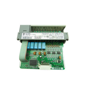
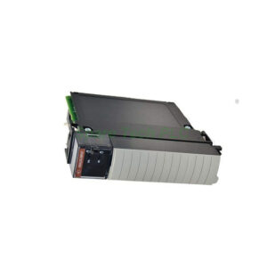
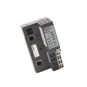
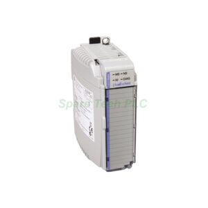
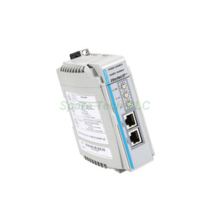
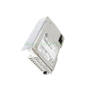
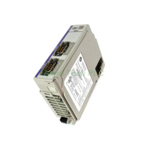
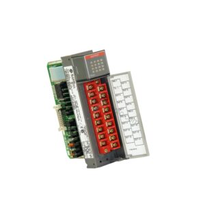
Allen-Bradley 1747-AENTR Ethernet/IP Communication Module
Product Introduction
The 1747-AENTR is a communication adapter for the SLC 500 platform. Its primary purpose is system migration. You can replace an existing SLC 500 processor with this module. Then a CompactLogix or ControlLogix controller can control all I/O modules in the SLC chassis. This approach extends the life of legacy 1746 I/O while upgrading to modern Logix control.
Technical Specifications of the 1747-AENTR
This module belongs to the SLC 500 series. It mounts in slot 0 (the leftmost slot) of any SLC 500 chassis. The 1747-AENTR draws 470 mA from the 5V DC backplane. Thermal dissipation is 2.49 W (8.5 BTU/hr).
Furthermore, it provides two embedded Ethernet ports. Both ports support 10/100 Mbps communication. You can configure each port for half or full duplex. The connector type is RJ-45 using Category 5 cable (shielded or unshielded).
The module supports multiple network topologies. For instance, you can use star, tree, linear (daisy chain), or ring topology. This flexibility simplifies machine layout and network redundancy.
Additionally, the 1747-AENTR functions as a CIP server on the Ethernet side and as an SLC host on the 1746 backplane. It replaces older adapters like the 1747-ASB, 1747-ACN15, or 1747-ACNR15.
Mechanical and Environmental Parameters
The 1747-AENTR operates from 0°C to 60°C (32°F to 140°F). Non‑operating temperature ranges from -40°C to 85°C (-40°F to 185°F). Relative humidity is 5% to 95% without condensation.
Its dimensions are 145.3 x 34.8 x 130.8 mm (5.72 x 1.37 x 5.15 inches). Weight is approximately 168 grams (0.37 pounds). Isolation voltage is 50V continuous, with basic insulation type. The enclosure is rated Open.
Installation Guidelines
You must install the 1747-AENTR into slot 0 of any SLC 500 chassis. First, remove the existing SLC processor if present. Next, configure the IP address, subnet mask, and optional gateway address before installation. You can do this using a temporary connection or a configuration tool.
Then, insert the 1747-AENTR into slot 0 and tighten the retaining screws. After that, connect Ethernet cables to one or both RJ-45 ports. Finally, power up the chassis and verify communication with the Logix controller via Studio 5000.
For ring topology, you must enable the ring protocol in the module configuration. For linear or star topology, standard Ethernet switching applies.
Packaging List
Note: No certificate or warranty document is included in the package.
Shipping Methods
We ship worldwide via FedEx, UPS, or DHL. Tracking number provided within 24 hours after dispatch.
Frequently Asked Questions (FAQ)
1. Can I keep my existing SLC 500 processor after installing the 1747-AENTR?
No. The 1747-AENTR physically replaces the processor in slot 0. You cannot have both in the same chassis.
2. Does the 1747-AENTR work with any Logix controller?
Yes. It works with CompactLogix and ControlLogix controllers over Ethernet/IP. The Logix processor sees the SLC I/O as local or remote racks.
3. What is the maximum cable length between the 1747-AENTR and an Ethernet switch?
Using Category 5 cable, the maximum segment length is 100 meters (328 feet).
4. How do I assign an IP address to the 1747-AENTR?
You can use BOOTP/DHCP server (Rockwell BootP utility), a web browser (via temporary IP), or RSLinx Classic with the module’s MAC address.
5. Is the 1747-AENTR compatible with all 1746 I/O modules?
Most standard 1746 digital and analog I/O modules work. However, some specialty modules (like certain motion or high‑speed counter modules) may have limitations. Always check the module’s migration guide.