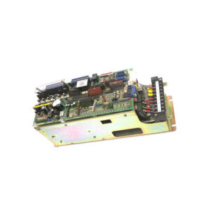
STBEPI2145K Interface Module Technical Guide for Motor Starters
Product Introduction
The Schneider Electric STBEPI2145K is a parallel interface kit purpose-built for the Modicon STB distributed I/O platform. This module provides 12 input channels and 8 output channels, supporting 24V DC operation. The STBEPI2145K serves as the communication bridge between the Modicon STB island and TeSys U starter-controllers or TeSys Quickfit prewired motor starters. Each RJ45 port on the STBEPI2145K delivers 2 outputs (forward and reverse commands) and 3 inputs (motor starter status signals), totaling 8 outputs and 12 inputs per module. This STBEPI2145K kit includes the terminal spring clamp connector, STBXBA3000 mounting base, terminal screw-type connector, and the STBEPI2145 module itself. Field engineers commonly deploy this STBEPI2145K interface for packaging, bottling, assembly, distribution, textile, printing, and semiconductor machinery applications.
Core Value
The STBEPI2145K eliminates complex hardwiring between PLC systems and motor starters. Specifically, this parallel interface kit allows direct connection to up to 4 TeSys U starter-controllers or 4 TeSys Quickfit direct motor starters. For reversing applications, the STBEPI2145K supports 2 TeSys Quickfit reversing starters. This module significantly reduces installation time and panel space requirements. Moreover, the STBEPI2145K enables hot swapping for standard NIMs, minimizing production downtime during maintenance. The integrated protection features—including overload protection, short-circuit protection, and resistor-limited input protection—safeguard both the STBEPI2145K module and connected field devices.
Technical Insights
The STBEPI2145K operates on a 24V DC supply voltage and draws a maximum of 100mA at 24V DC for the sensor bus, plus 220mA at 24V DC for the actuator bus during the 150ms startup period. The logic bus consumes 100mA at 5V DC. This parallel interface kit accepts input voltage limits of 15 to 30V for state 1 and -3 to 5V for state 0, with guaranteed currents of ≥2mA for state 1 and ≤0.5mA for state 0. The STBEPI2145K also features four RJ45 connectors for electrical connections and includes LED indicators for module status (RDY green), module error (ERR red), switch position (S1 and S2 green), and output status. Furthermore, this STBEPI2145K module supports user-configurable fallback states for standard NIMs, offering flexibility in fault conditions.
Installation & Maintenance
Installing the STBEPI2145K requires mounting the STBXBA3000 base onto a DIN rail first. Then, snap the STBEPI2145 module onto the base and secure it with the two locking latches. Connect the power distribution module STBPDT3100 or STBPDT3105 to supply the 24V DC power. For connecting to TeSys U starters, use RJ45 cables such as LU9R03 (0.3m), LU9R10 (1m), or LU9R30 (3m). Note that a forward-only TeSys U starter needs one cable, while a reversing starter requires two cables. The STBEPI2145K also accommodates mixed TeSys U and TeSys Quickfit connections across available RJ45 ports. For maintenance, periodically check the LED indicators for fault conditions. Replace the STBEPI2145K module immediately if the ERR LED remains lit after a power cycle.

Buyer’s Guide FAQ
Q1: What is the STBEPI2145K used for?
A1: The STBEPI2145K connects Modicon STB distributed I/O systems to TeSys U and TeSys Quickfit motor starters, providing parallel interface functionality for motor control applications.
Q2: How many motor starters can the STBEPI2145K support?
A2: This STBEPI2145K supports up to 4 TeSys U starter-controllers or 4 TeSys Quickfit direct starters, or 2 TeSys Quickfit reversing starters per module.
Q3: What cable types work with the STBEPI2145K?
A3: Use shielded RJ45 cables like LU9R03, LU9R10, or LU9R30. The STBEPI2145K requires these cables for reliable communication between the island and starters.
Q4: Does the STBEPI2145K support hot swapping?
A4: Yes. The STBEPI2145K enables hot swapping for standard NIMs, allowing you to replace modules without powering down the entire system.
Q5: What are the power requirements for the STBEPI2145K?
A5: The STBEPI2145K needs 24V DC for sensor and actuator buses, drawing 100mA and 220mA respectively, plus 100mA at 5V DC for the logic bus.