Product Introduction
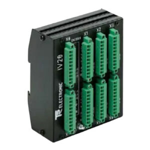
The TR PT15/2 490-00105 (Art.-No.:490-00105) is a practical switch cabinet module from TR Electronic, a trusted provider of industrial sensor and auxiliary equipment. It is part of the PT15 series, designed specifically for encoder and linear encoder reprogramming in industrial control systems. This module acts as a critical connecting bridge, simplifying the connection between programming devices, encoders, and control systems.
It features two 16-pole terminal blocks to accommodate incoming and extending signal lines. This design ensures organized and secure signal transmission during programming. The TR PT15/2 490-00105 also includes a 15-pole SUB-D socket, which connects to the PT-100 programming terminal for seamless programming operations.
This module is engineered to lock onto commercially available EN-mounting rails. This feature simplifies installation in standard switch cabinets, saving time and effort for on-site technicians. It suits a wide range of industrial scenarios, including manufacturing, automation, and control systems where encoder reprogramming is a regular task.
Technical Specifications
Core Function and Design
The TR PT15/2 490-00105 primarily functions as a connecting link for encoder reprogramming. It connects programmers (PT-100-N or PC), encoders, and control systems, enabling smooth data transmission during reprogramming. Its compact design fits easily into standard switch cabinets, making it ideal for space-constrained environments.
It comes with two 16-pole terminal blocks, which neatly organize incoming and extending signal lines. This organization prevents signal interference and ensures reliable connections. The 15-pole SUB-D socket provides a dedicated interface for the PT-100 programming terminal, ensuring compatibility and stable communication.
A key design feature is its ability to lock onto commercially available EN-mounting rails. This allows for quick, secure installation without additional custom mounting hardware. The module’s sturdy construction ensures it stays firmly in place even in vibrating industrial environments.
Communication and Data Interface
The TR PT15/2 490-00105 has clearly defined terminal and pin functions for communication and data transmission. Terminal/Pin 1 serves dual purposes: it acts as Data PT – for PT-100 connections and Data PT – / address – for PC adapter connections. This versatility allows it to work with both PT-100 programmers and PC adapters.
Terminal/Pin 2 also has dual functions: it acts as Data PT + for PT-100 connections and Data PT + / address + for PC adapter connections. Terminals/Pins 3 and 4 are not connected when using a PT-100. For PC adapter connections, they function as Data – and Data + respectively.
An important hint: When using a PC adapter, connect pins 3 and 4 only with signals ≤ 5V. This prevents damage to the module and ensures safe, reliable data transmission. Unconnected pins can be used for encoder or signal transmission, adding flexibility to the module’s use.
Specialized Output and Power Supply
Terminal/Pin 7 of the TR PT15/2 490-00105 provides the PT switch output for TA-Mini. This function remains consistent whether using a PT-100 or PC adapter, ensuring compatibility across different programming setups. It delivers reliable switch output for seamless integration with TA-Mini devices.
For power supply, Terminal/Pin 14 is designated for US 11-27 V DC (positive supply voltage input). Terminal/Pin 15 is for 0V, GND (power supply ground). This voltage range is compatible with most industrial power systems, ensuring stable operation in diverse industrial environments.
The module’s power supply design prioritizes safety and efficiency, preventing voltage fluctuations from affecting performance. It draws minimal power, making it suitable for long-term continuous operation in switch cabinets.
Grounding, Shielding and Unused Terminals
Terminal/Pin 16 and the SUB-D case are designated for the shield. You must connect them to the cable shield and the connector case. This step ensures electromagnetic compatibility (EMC) and maintains signal integrity, reducing interference from external electrical sources.
Terminals/Pins 5, 6, 8, 9, 10, 11, 12, and 13 are not connected in either operating mode (PT-100 or PC adapter). You should leave these terminals open to avoid signal interference or damage to the module. Do not connect any wires to these unused terminals during installation.
Mechanical and Environmental Parameters
Mechanical Parameters
The TR PT15/2 490-00105 has a compact, lightweight design with a gross weight of 0.6 kg. This makes it easy to handle and install in switch cabinets. Its dimensions are optimized for EN-mounting rails, ensuring a perfect fit with standard rail systems.
The module features two 16-pole terminal blocks and a 15-pole SUB-D socket, all positioned for easy access during wiring. The terminal blocks have clear labeling for each pin, simplifying installation and troubleshooting. The EN-mounting rail lock ensures secure attachment, preventing movement during operation.
Its sturdy plastic housing protects internal components from physical damage. The housing is designed to withstand typical industrial handling, ensuring long-term durability in switch cabinet environments.
Environmental Parameters
The TR PT15/2 490-00105 performs reliably in standard industrial environments. Its operating temperature range suits most switch cabinet conditions, ensuring stable performance in both cool and warm settings. It can tolerate minor temperature fluctuations without affecting functionality.
The module’s shielding design (Terminal/Pin 16 and SUB-D case) provides strong electromagnetic interference (EMI) protection. This ensures signal integrity even in environments with high electrical noise, such as factories with heavy machinery.
It can withstand typical industrial vibration, maintaining stable connections and performance. The housing provides basic protection against dust and minor moisture, keeping internal components safe in clean switch cabinet environments. The storage temperature range allows safe storage when the module is not in use.
Installation Guide
Preparation Steps
Installing the TR PT15/2 490-00105 is straightforward with proper preparation. First, gather the necessary tools: a screwdriver, wire stripper, and cable cutter. Before installation, inspect the module for any damage during transportation.
Check that the model (TR PT15/2 490-00105, Art.-No.:490-00105) matches your application requirements. Prepare the EN-mounting rail in the switch cabinet, ensuring it is clean and free of debris. Also, prepare the signal cables and power supply cable, ensuring they meet the module’s specifications.
Review the pin functions to avoid wiring errors. Make sure you have the PT-100 programming terminal or PC adapter ready, depending on your setup.
Mounting the Module
The TR PT15/2 490-00105 is designed to lock onto commercially available EN-mounting rails. Align the module with the rail and push it firmly until it clicks into place. Ensure the module is securely attached and does not move or wobble.
Position the module in a location within the switch cabinet that allows easy access to the terminal blocks and SUB-D socket. Leave enough space around the module for wiring and future maintenance. Avoid placing it near high-temperature components or sources of strong electromagnetic interference.
Wiring and Connection
Start by connecting the power supply cable to Terminals/Pins 14 and 15. Connect the positive supply voltage (11-27 V DC) to Terminal/Pin 14. Connect the power supply ground (0V, GND) to Terminal/Pin 15. Double-check the polarity to avoid damaging the module.
Next, connect the signal lines to the two 16-pole terminal blocks. Use one terminal block for incoming signal lines and the other for extending signal lines. Follow the pin function guide to connect the correct wires to each terminal.
If using a PT-100 programming terminal, connect it to the 15-pole SUB-D socket. If using a PC adapter, connect it to the SUB-D socket and ensure pins 3 and 4 only receive signals ≤ 5V. Connect the cable shield to Terminal/Pin 16 and the SUB-D case to ensure EMC and signal integrity.
Leave Terminals/Pins 5, 6, 8, 9, 10, 11, 12, and 13 open. Do not connect any wires to these unused terminals.
Testing and Usage Notes
After wiring, power on the module and the connected devices (programmer, encoder, control system). Perform a test to verify smooth communication and data transmission. Check that the PT switch output for TA-Mini (Terminal/Pin 7) functions correctly.
During use, never connect signals >5V to pins 3 and 4 when using a PC adapter. This can damage the module. Ensure all connections are tight to prevent poor contact and signal loss.
Regularly inspect the module and wiring for signs of damage or wear. Clean the terminal blocks and SUB-D socket periodically to remove dust and debris. If you notice any abnormalities, power off the module and troubleshoot the connections or replace the module if necessary.
Packaging List
1 x TR Electronic TR PT15/2 490-00105 Switch Cabinet Module (Art.-No.:490-00105)
2 x 16-Pole Terminal Block Covers
1 x 15-Pole SUB-D Socket Cover
4 x Mounting Clips (for EN-mounting rail)
1 x Installation Manual (English Version)
1 x Wiring Diagram (English Version)
FAQ
Q1: What is the main function of the TR PT15/2 490-00105 switch cabinet module?
A1: This module acts as a connecting link between programmer (PT-100-N/PC), encoder, and control system. It enables reprogramming of encoders or linear encoders, with two 16-pole terminal blocks for signal lines and a 15-pole SUB-D socket for programming devices.
Q2: Can the TR PT15/2 490-00105 be mounted on any EN-mounting rail?
A2: Yes, it can. The TR PT15/2 490-00105 is designed to lock onto commercially available EN-mounting rails. This ensures compatibility with standard switch cabinet rail systems, simplifying installation.
Q3: What power supply does the TR PT15/2 490-00105 require?
A3: It requires a 11-27 V DC power supply. Terminal/Pin 14 is for positive supply voltage (US 11-27 V DC), and Terminal/Pin 15 is for power supply ground (0V, GND). This range fits most industrial power systems.
Q4: What should I note when using a PC adapter with this module?
A4: When using a PC adapter, connect pins 3 and 4 only with signals ≤ 5V. Exceeding this voltage can damage the module. Also, ensure pins 1 and 2 are correctly connected as Data PT – / address – and Data PT + / address + respectively.
Q5: What are the unused terminals on the TR PT15/2 490-00105, and how should I handle them?
A5: Terminals/Pins 5, 6, 8, 9, 10, 11, 12, and 13 are unused in both operating modes. You should leave these terminals open—do not connect any wires to them to avoid signal interference or module damage.