Product Introduction
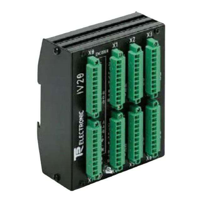
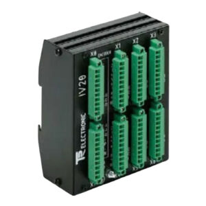
The TR IV-20 (490-00006) is a robust pulse distributor module designed for industrial automation systems. It specializes in splitting and distributing incremental encoder signals (A/B/Z or K0/K1/K2 differential pairs) from one source to multiple control devices, ensuring signal integrity across long cables and different control systems.
This module accepts a single incremental encoder input and provides six galvanically isolated output channels, supporting flexible signal level conversion (5V TTL differential to 11-30V push-pull, or vice versa). It features four configurable operating modes to match various encoder types (5V differential, 11-30V single-ended, push-pull, open collector).
With full electrical isolation between input, outputs, and power supply, the IV-20 eliminates ground loops and electrical interference, making it ideal for heavy industry, robotics, machine tools, and conveyor systems where reliable signal distribution is critical.
Technical Specifications
Core Functional Parameters
- Input Interface: Incremental encoder (K0, /K0; K1, /K1; K2, /K2) – differential/single-ended
- Output Channels: 6 independent channels (duplicated encoder signals)
- Operating Modes: 4 programmable modes (via X7 connector)
- Mode 1: 5V differential input → 5V differential output
- Mode 2: 11-30V single-ended → 11-30V push-pull
- Mode 3: 11-30V push-pull → 11-30V push-pull
- Mode 4: Open collector/emitter → 11-30V push-pull
- Signal Levels:
- Input: 5V differential (RS422) or 11-30V single-ended
- Output: 5V TTL differential or 11-30V push-pull (configurable via jumpers)
- Input Current: 1.5mA (min) / 20mA (max) per channel
- Switching Frequency: Up to 300 kHz (compatible with high-speed encoders)
- Isolation Voltage: 2.5kV RMS (input-output-power) – full galvanic isolation
Electrical Specifications
- Supply Voltage: 11–30 V DC (nominal 24V DC)
- Power Dissipation: < 4 Watts (no load)
- Reverse Polarity Protection: Yes (prevents damage from wrong wiring)
- Overvoltage/ESD Protection: IEC 61000-4-2 (ESD), VDE 0113 (surge)
- Logic Levels:
- Input Low: < +2V ; High: > +8V
- Output Low: < 1V ; High: > (Vsupply-2V)
Mechanical & Environmental
- Dimensions: Standard DIN rail mount (35mm)
- Connectors:
- X0: Input (encoder) – 10-pin terminal block
- X1: Output (6 channels) – 25-pin terminal block
- X7: Mode selector – 8-pin connector
- Operating Temp: -20°C ~ +60°C
- Storage Temp: -30°C ~ +85°C
- Humidity: 98% (non-condensing)
- Vibration Resistance: 10–2000 Hz, 10g (IEC 60068-2-6)
- Protection: IP20 (panel/din rail mount)
Pinout & Configuration
Input X0 (10-pin)
- K0 (A+)
- /K0 (A-)
- K1 (B+)
- /K1 (B-)
- K2 (Z+)
- /K2 (Z-)
- GND (input)
- +5V (optional, for encoder)
- NC
- NC
Output X1 (25-pin)
- Channels 1–6: K0, /K0, K1, /K1, K2, /K2 (duplicated)
- Common GND for outputs (galvanically separated from input)
Mode Selector X7
- Pins configure operating mode and output voltage (5V/24V) via internal jumpers
Key Features & Advantages
- Signal Duplication: One encoder → six isolated outputs for multi-controller systems
- Level Conversion: Auto-convert 5V ↔ 24V signals without external adapters
- Galvanic Isolation: 2.5kV isolation eliminates ground loops and electrical noise
- Wide Compatibility: Works with all standard incremental encoders (HTL/TTL/RS422)
- Easy Configuration: 4 modes via DIP switches/jumpers; no software needed
- Industrial Durability: ESD/surge protection, wide temp range, DIN rail mount
- Space-Saving: Compact design for control cabinets
Applications
- Multi-Controller Systems: Share one encoder with PLC, drive, HMI, and counter
- Long-Distance Transmission: Boost signals for cable runs >50m
- Voltage Level Matching: Bridge 5V TTL and 24V HTL systems
- Noise Reduction: Isolate sensitive encoder signals from high-power machinery
- Machine Safety: Redundant position feedback for safety circuits
- Conveyor Systems: Distributed position monitoring across long lines
Installation Guide
Mounting
- Snap onto standard 35mm DIN rail in control cabinet
- Ensure adequate ventilation (max 4W dissipation)
- Mount vertically for optimal heat dissipation
Wiring
- Input (X0): Connect encoder A/B/Z differential pairs
- Output (X1): Wire to 1–6 control devices (PLC, drive, etc.)
- Power: Connect 11–30V DC to terminal block (observe polarity)
- Mode (X7): Set jumpers for desired operating mode (see manual)
Configuration
- Set operating mode via X7 jumpers (match encoder type)
- Set output voltage (5V/24V) via internal jumpers
- Verify LED indicators (Power: green; Signal: yellow)
- Test encoder movement – all outputs should mirror input pulses
Packaging List
1 x TR Electronic IV-20 (490-00006) Pulse Distributor
1 x DIN Rail Mounting Clip
1 x Terminal Block Screwdriver
1 x User Manual (English)
1 x Wiring Diagram
1 x Configuration Guide
FAQ
Q1: What is the difference between IV-20 and IV-30?A1: IV-20 (490-00006) supports 5V/11-30V signals with 6 non-isolated outputs (common ground). IV-30 has full galvanic isolation per channel and RS422 outputs.
Q2: Can I use this with single-ended (HTL) encoders?A2: Yes – Modes 2–4 support 11–30V single-ended (HTL) inputs and push-pull outputs.
Q3: What is the maximum encoder speed supported?A3: Up to 300 kHz input frequency, suitable for encoders up to 6000 RPM at 1024 PPR.
Q4: Is the output signal inverted or same as input?A4: Outputs are non-inverted copies of input signals. Phase relationship (A leading B) is preserved.
Q5: Can I power the encoder from the IV-20?A5: Yes – X0 provides optional +5V (up to 100mA) for encoder power supply.