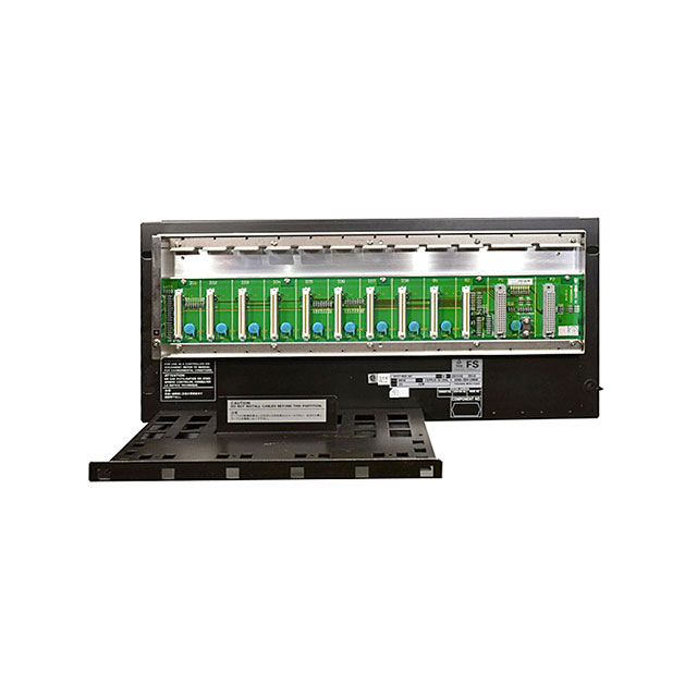
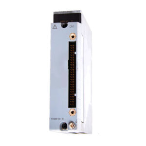
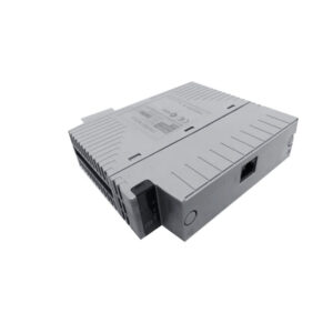
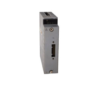
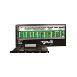
SPW482-53 Yokogawa Power Supply Module
Product Introduction
The Yokogawa SPW482-53 is a specialized power management component designed for critical safety instrumented systems. Primarily, this module connects to a 100 to 120 V AC or 220 to 240 V AC source to provide power. For instance, the hardware supplies insulated +5 V and +24 V DC to all installed I/O modules through the backplane. Furthermore, the SPW482-53 supports dual-redundant operation, ensuring that the safety system remains active even if one power unit fails. Additionally, this "-53" variant features an ISA Standard G3 coating for superior corrosion resistance in harsh industrial environments. Therefore, the module is a dependable choice for facilities operating in extreme temperatures ranging from -20 to 70 °C. Specifically, the unit includes front-panel status LEDs to provide immediate visual feedback on output health.
Technical Specifications
The SPW482-53 utilizes advanced insulation and regulation circuitry to protect sensitive I/O cards from main source fluctuations. Specifically, the module receives the specified voltage through a standard terminal block featuring Line, Neutral, and Grounding ports. Meanwhile, the output voltage for logic processing is held strictly at +5 V DC for system stability. Moreover, the field-side power is maintained at +24 V DC to drive various sensors and actuators. Specifically, the hardware allows technicians to measure these voltages directly using integrated Check Terminals for maintenance purposes. Furthermore, the unit is a standard type with no explosion protection, making it ideal for safe-area control rooms. Consequently, the SPW482-53 provides the steady electrical foundation required for high-integrity safety loops.
Mechanical and Environmental Parameters
The physical build of the SPW482-53 focuses on a compact footprint and high thermal efficiency for long-term use. For instance, the module weighs only 0.34 kg, allowing for easy handling and installation into ProSafe-RS racks. Additionally, the ISA Standard G3 conformal coating protects internal electronics against corrosive gases like hydrogen sulfide. Specifically, the module is engineered to operate reliably in a wide temperature range of -20 to 70 °C. Meanwhile, the front-panel "SYS" and "FLD" LEDs illuminate only when their respective voltage outputs are within proper limits. Furthermore, the dual-redundant insulated output capability ensures that power faults do not propagate through the system backplane. Therefore, the SPW482-53 ensures the continuous uptime of critical safety control and node unit hardware.
Installation Guide
Installing the SPW482-53 requires careful attention to the wiring of the main source and the grounding terminal. First, ensure that the input power source matches the module's rated voltage of 100-120V or 220-240V AC. Specifically, connect the Line (L) and Neutral (N) wires to the designated ports and secure the grounding terminal. Next, slide the module into the power supply slot of the field control or node unit until it clicks. Furthermore, verify that the "SYS" LED turns ON, indicating that the +5 V logic power is functioning correctly. Specifically, confirm that the "FLD" LED is also active, signifying that +24 V is ready for field I/O modules. Finally, use a multimeter on the check terminals to verify that the output voltages meet the ± 5% tolerance.
Packaging List
1 x Yokogawa SPW482-53 Power Supply Module
1 x Hardware Mounting Guide
Protective Anti-static Packaging
Shipping Method: Fedex, UPS, DHL
FAQ
1. What do the SYS and FLD LEDs indicate on the SPW482-53?
The SYS lamp indicates +5 V logic power is active, while the FLD lamp indicates +24 V field power is output properly.
2. Can I use the SPW482-53 in a redundant configuration?
Yes, the module is specifically designed to support dual-redundant insulated output operation for enhanced system reliability.
3. What is the temperature range for this specific model?
The suffix code "3" denotes that this unit is rated for an extended temperature range of -20 to 70 °C.
4. What does the ISA Standard G3 coating protect against?
The G3 coating protects the internal circuitry from corrosion caused by moisture and harsh industrial gases like $H_2S$.
5. How do I verify the output voltage during maintenance?
Technicians can measure the actual +5 V and +24 V DC outputs using the dedicated Check Terminals on the front panel.