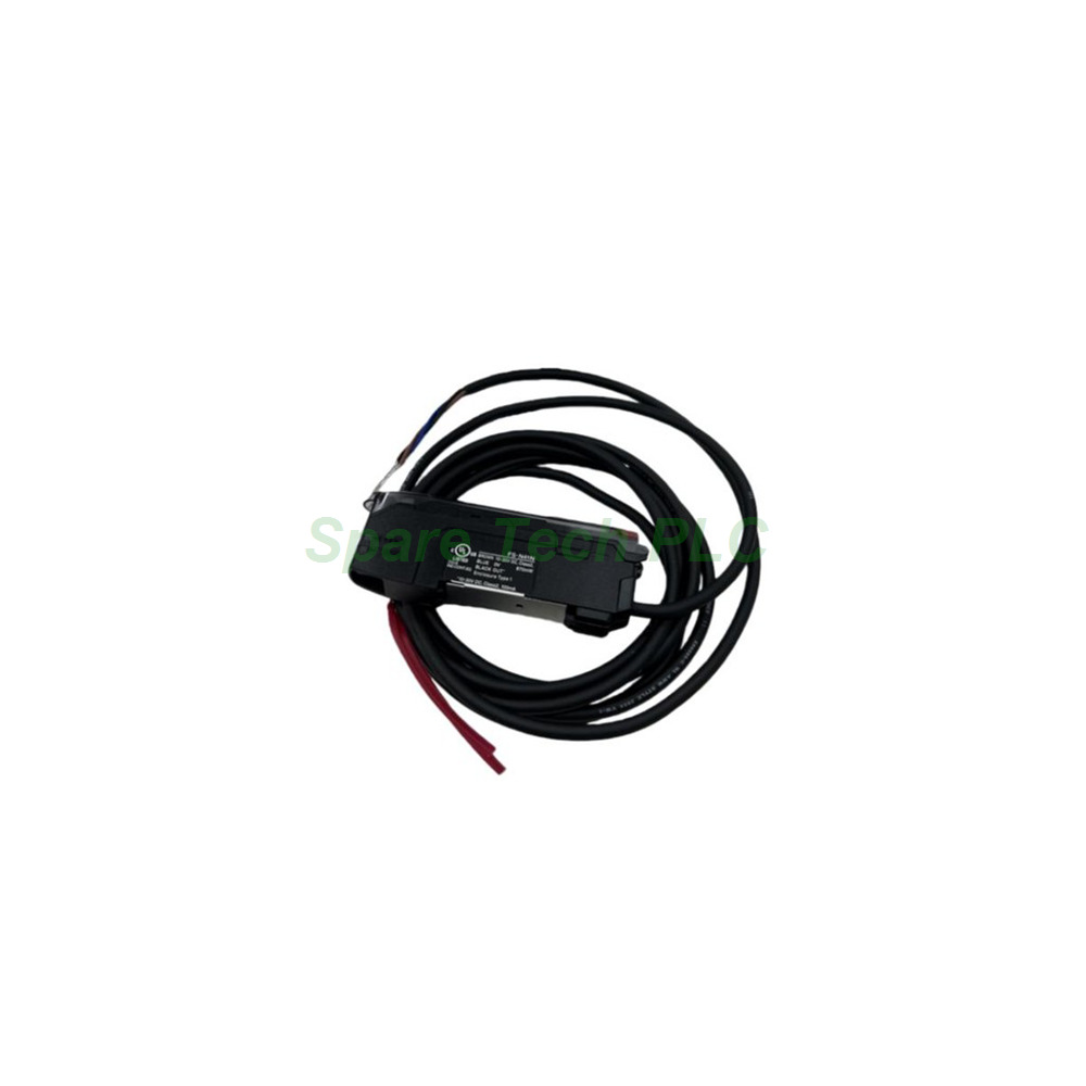
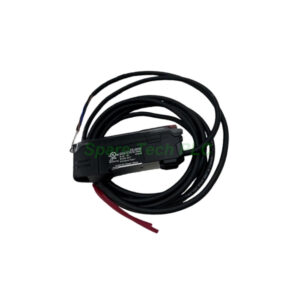
Keyence FS-N41P PNP Digital Fiber Sensor Amplifier
The Keyence FS-N41P serves as the main unit of the FS-N40 series in PNP wiring environments. It carries one PNP control output and drives connected expansion amplifiers. Because PNP outputs sink current to ground, they match many European and North American PLC input cards. Therefore, the FS-N41P fits panels built around positive-switching logic.
Technical Specifications
A red four-element LED with a 660 nm wavelength supplies the light source. This element design keeps emission steady across long fiber cables. The amplifier provides eight response modes, from 23 µs (S-HSPD) to 64 ms (TERA). As a result, one unit covers fast registration marks and slow, contaminated targets alike.
Response time: 23 µs (S-HSPD) / 50 µs (HSPD) / 250 µs (FINE) / 500 µs (TURBO) / 1 ms (SUPER) / 4 ms (ULTRA) / 16 ms (MEGA) / 64 ms (TERA)
Control outputs: 1 (PNP open-collector)
Output rating: 30 V max, 100 mA max per output
Residual voltage: 1.6 V at 10 mA; 2.2 V at 10–100 mA
External input: none on this main unit
Unit expansion: up to 16 units (17 total including main; dual-output counts as 2)
Electrical and I/O Details
The supply voltage ranges from 10 to 30 VDC with 10% ripple P-P or less. A Class 2 or LPS source is mandatory. Power consumption sits at 910 mW or less, which equals 36 mA at 24 V. With ECO ON it drops to 840 mW, and ECO FULL lowers it to 750 mW. Furthermore, the open-collector PNP output handles 100 mA, enough for most PLC inputs and interface relays.
Mechanical and Environmental Parameters
The main unit weighs about 78 g. Operating temperature spans -20 to +55 °C without freezing. Thermal derating applies once users add expansion units to the group. The compact housing mounts on standard DIN rail and suits crowded control cabinets.
Installation Guide
First, clip the main unit onto the DIN rail at the left end of the amplifier group. Next, connect the 10–30 VDC supply and route the PNP output to the PLC input. Then, attach expansion units on the right side through the expansion connector. After that, set thresholds and response modes using the OLED display. Finally, test detection with the actual workpiece before starting production.
Keep fiber cables clear of high-voltage lines and respect the minimum bend radius. For long output runs, verify the voltage drop remains within the load tolerance.
Packaging List
FAQ
Q1: What is the main difference between the FS-N41P and the FS-N42N?
A: The FS-N41P is a main unit with a PNP output. The FS-N42N is an expansion unit with an NPN output and needs a main amplifier to operate.
Q2: Why choose PNP instead of NPN?
A: PNP outputs switch the positive supply, which matches many European and North American PLC input modules. The choice usually follows the panel wiring standard.
Q3: How many expansion units can this main unit support?
A: It supports up to 16 expansion units, giving 17 total including the main unit. A dual-output model counts as two units.
Q4: Which response mode should I select?
A: Use 23 µs for high-speed detection. Choose 4 ms or slower modes when targets move slowly or when dust and vibration reduce signal stability.
Q5: How do you ship this amplifier?
A: We ship by Fedex, UPS, or DHL. Most orders leave the warehouse within 1–3 business days after payment confirmation.