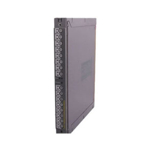
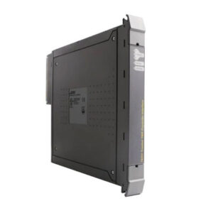
Product Introduction
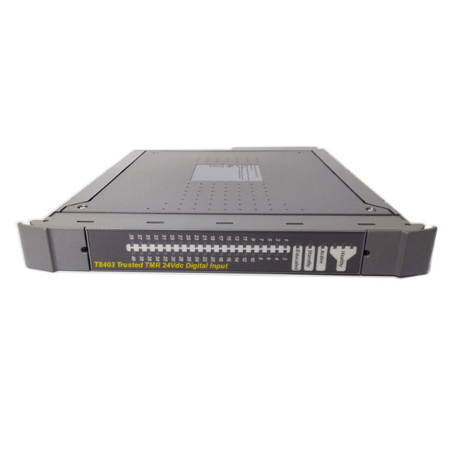
The ICS Triplex T8403 is a high-performance, safety-grade digital input module belonging to the ICS Triplex Trusted TMR Series, a core product for industrial safety automation. Developed by ICS Triplex (a brand under Rockwell Automation), this module is engineered with Triple Modular Redundancy (TMR) architecture to eliminate single-point failures, ensuring ultra-high reliability and fault tolerance—critical for mission-critical industrial applications.
As a 40-channel digital input module, it is designed to collect and transmit digital input signals from various industrial sensors, switches, and safety devices to the main control system. Its TMR design replicates critical components three times, with built-in voting logic to ensure accurate signal processing even if one module fails. This makes the T8403 ideal for use in safety instrumented systems (SIS), emergency shutdown systems (ESD), and other critical automation setups where system failure could lead to safety hazards, production losses, or environmental damage.
The module supports a wide power supply range (20-32Vdc) with a 20W power rating, ensuring stable operation in fluctuating industrial power environments. It also features a broad input/output voltage range (0-40Vdc), compatible with most standard industrial digital input devices. With Ord/HazLoc/ATEX/IECEx certifications, it can be safely used in hazardous and non-hazardous industrial areas, including oil and gas, petrochemical, power generation, and chemical processing industries.
Technical Specifications
Core Functional Parameters
- Architecture: Triple Modular Redundancy (TMR) – ensures fault tolerance and high reliability
- Input Channels: 40 independent digital input channels (isolated)
- Input Type: Digital input (dry contact, NPN/PNP compatible)
- Input Voltage Range: 0-40Vdc (compatible with 24Vdc standard industrial signals)
- Input Current: Typical 5mA per channel (max 10mA)
- Response Time: ≤10ms (configurable, adjustable for different application needs)
- Isolation: Channel-to-channel isolation (2.5kV RMS), input-to-power isolation (2.5kV RMS) – prevents signal interference and ground loops
Electrical Specifications
- Supply Voltage: 20-32Vdc (nominal 24Vdc)
- Power Consumption: 20W (max, full load)
- Reverse Polarity Protection: Yes – prevents damage from incorrect power wiring
- Overvoltage Protection: Built-in, compliant with IEC 61000-4-2 (ESD) and IEC 61000-4-5 (surge)
- Logic Levels:
- Input Low (OFF): ≤5Vdc
- Input High (ON): ≥18Vdc (24Vdc nominal)
- Diagnostic Features: Built-in self-diagnostics (channel fault, power fault, module fault) with LED indicators
Certification & Compliance
- Certifications: Ord/HazLoc/ATEX/IECEx – suitable for hazardous and non-hazardous areas
- Safety Standards: Complies with IEC 61508 (SIL 3), EN 50159 – meets high safety integrity requirements
- Environmental Standards: IEC 60068-2 (temperature, vibration, shock)
Mechanical & Environmental Parameters
Mechanical Parameters
- Dimensions: Standard 3U rack mount (compatible with ICS Triplex Trusted series cabinets)
- Connectors: 2 x 50-pin terminal blocks (for input signals and power supply)
- Mounting: Rack-mounted (compatible with standard industrial cabinets)
- Gross Weight: 0.34 kg
- Material: Industrial-grade metal housing (corrosion-resistant, EMI-shielded)
Environmental Parameters
- Operating Temperature: -40°C ~ +70°C (wide range for harsh industrial environments)
- Storage Temperature: -40°C ~ +85°C
- Relative Humidity: 0% ~ 95% (non-condensing)
- Vibration Resistance: 10-2000 Hz, 10g (IEC 60068-2-6)
- Shock Resistance: 50g (half sine, 11ms; IEC 60068-2-27)
- Protection Class: IP20 (panel/rack mount, suitable for control cabinets)
Key Features & Advantages
- TMR Architecture: Triple modular redundancy eliminates single-point failures, ensuring SIL 3 safety integrity and continuous operation even with component faults.
- 40-Channel Design: High channel density reduces cabinet space requirements, lowering installation costs for large-scale automation systems.
- Broad Compatibility: 0-40Vdc input range and 20-32Vdc power supply, compatible with most industrial digital input devices and power systems.
- Hazardous Area Certification: Ord/HazLoc/ATEX/IECEx certifications allow use in explosive and hazardous industrial environments (oil, gas, petrochemical).
- Built-in Diagnostics: Real-time self-diagnostics with LED indicators for quick fault identification, reducing downtime and maintenance costs.
- Isolation Protection: Channel-to-channel and input-to-power isolation prevents electrical interference and ground loops, ensuring signal integrity.
- Robust Design: Industrial-grade housing, wide temperature range, and vibration/shock resistance, suitable for harsh industrial conditions.
Applications
- Safety Instrumented Systems (SIS): Critical safety control in oil and gas, petrochemical, and chemical plants.
- Emergency Shutdown Systems (ESD): Reliable signal collection for emergency shutdown triggers.
- Power Generation: Turbine control, boiler safety, and auxiliary system monitoring.
- Petrochemical & Oil/Gas: Hazardous area process control, pipeline monitoring, and safety control.
- Industrial Automation: High-reliability digital input collection for manufacturing, mining, and heavy industry.
- Mission-Critical Systems: Any application where system failure could result in safety risks, production losses, or environmental harm.
Installation Guide
Preparation Steps
- Gather necessary tools: screwdriver, wire stripper, cable cutter, and torque wrench.
- Inspect the module for transportation damage (check housing, connectors, and LED indicators).
- Verify the module model (ICS Triplex T8403) and certifications match application requirements (hazardous/non-hazardous area).
- Prepare power supply (20-32Vdc) and input signal cables, ensuring they meet the module’s voltage and current specifications.
- Ensure the mounting rack is clean, stable, and compatible with 3U rack-mount standards.
Mounting
- Slide the T8403 module into the compatible ICS Triplex Trusted series rack or standard 3U rack.
- Secure the module to the rack using the provided mounting screws, tightening to the recommended torque (2-3 N·m) to ensure stability.
- Ensure there is adequate ventilation around the module (min 5cm clearance) to prevent overheating (max power dissipation 20W).
Wiring
- Power Supply Wiring: Connect the 20-32Vdc power supply to the dedicated power terminal block (positive and negative poles must be correctly aligned to avoid damage).
- Input Signal Wiring: Connect digital input devices (sensors, switches) to the 40-channel terminal block. Each channel is independent; ensure correct wiring to the corresponding channel pin (refer to the wiring diagram).
- Isolation Notes: Keep input signal cables separate from power cables to avoid electromagnetic interference. Use shielded cables for long-distance wiring, and connect the cable shield to the module’s ground terminal.
- Diagnostic Wiring: If connecting to a control system for diagnostic feedback, wire the module’s diagnostic output pins to the system’s corresponding interface.
Testing & Configuration
- Power on the module and the control system. Check the power LED indicator (green = normal power supply).
- Verify each input channel by activating the connected digital device; the corresponding channel LED should light up (red = signal ON, green = signal OFF).
- Test the self-diagnostic function by simulating a fault (e.g., disconnecting a signal cable) and confirm the fault LED indicator activates, and the diagnostic signal is transmitted to the control system.
- Configure the response time (if adjustable) via the control system to match the application’s requirements.
Usage Notes
- Do not exceed the input voltage range (0-40Vdc) or power supply range (20-32Vdc), as this may damage the module.
- Ensure proper grounding to maintain isolation and signal integrity, especially in hazardous areas.
- Regularly inspect the module’s LED indicators for fault signals and perform periodic maintenance (cleaning, wiring check).
- Do not install the module in areas with direct sunlight, excessive dust, or moisture (beyond IP20 protection limits).
- When replacing the module, ensure the new module has the same model and certifications to maintain system compatibility and safety integrity.
Packaging List
1 x ICS Triplex T8403 Trusted TMR 24Vdc Digital Input Module
2 x 50-Pin Terminal Block Covers
4 x Mounting Screws (M3 x 8 mm)
1 x Power Supply Cable (Length: 1.5 meters)
1 x Input Signal Cable (Length: 2 meters)
1 x Installation Manual (English Version)
1 x Wiring Diagram (English Version)
1 x Certification Document (Ord/HazLoc/ATEX/IECEx)
FAQ
Q1: What is the TMR architecture of the ICS Triplex T8403, and what is its purpose?A1: TMR (Triple Modular Redundancy) means the module has three identical independent circuits for signal processing. It uses voting logic to ensure accurate output—even if one circuit fails, the other two work normally, eliminating single-point failures and ensuring SIL 3 safety integrity for critical applications.
Q2: Can the T8403 be used in hazardous areas?A2: Yes. The ICS Triplex T8403 holds Ord/HazLoc/ATEX/IECEx certifications, making it suitable for use in both hazardous and non-hazardous industrial areas, such as oil and gas, petrochemical plants.
Q3: What is the input voltage range of the T8403, and is it compatible with 24Vdc sensors?A3: The input voltage range is 0-40Vdc, which is fully compatible with standard 24Vdc industrial digital sensors, switches, and safety devices.
Q4: How many input channels does the T8403 have, and are they isolated?A4: The T8403 has 40 independent digital input channels, with channel-to-channel isolation (2.5kV RMS) and input-to-power isolation, preventing signal interference and ground loops.
Q5: What safety standards does the T8403 comply with?A5: It complies with IEC 61508 (SIL 3) and EN 50159 standards, meeting high safety integrity requirements for mission-critical safety automation systems.