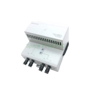
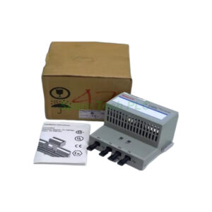
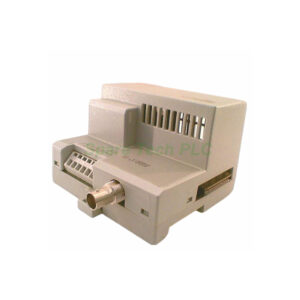
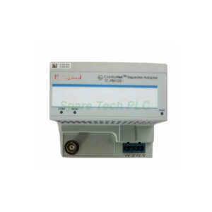
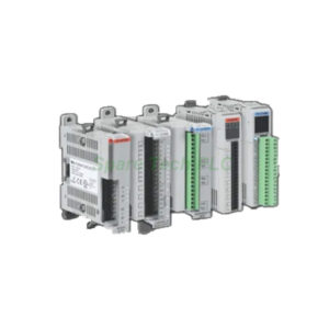
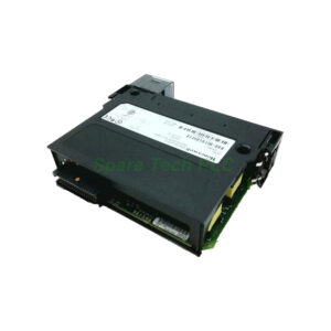
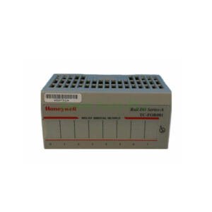
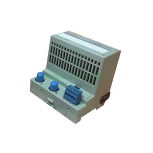
Honeywell TC-PTBC11 Terminal Base with Screw Clamps for I/O Modules
Product Introduction
The Honeywell TC-PTBC11 serves as a robust mounting and wiring platform for a single I/O module. You must mechanically key this terminal base before wiring. This feature prevents incorrect module insertion. The base accepts intrinsically safe power supply channels with ratings of Ui 10Vdc and Ii 2.5A.
Honeywell TC-PTBC11 offers 52 screw terminals in total. One row has 16 terminals, and two rows have 18 each. Use terminals +50 and -51 to daisy chain power to another terminal base. Do not connect anything to terminals 36 and 49. The internal bus uses a vendor-specific 16-pole plug and socket with Ui ≤ 10Vdc and Ii ≤ 400mA.
Additionally, the I/O assignments depend on the specific I/O module installed. Always refer to your I/O module specifications for correct wiring. The Honeywell TC-PTBC11 supports wire cross sections from 0.2 to 2.5mm². You can insert up to two cables of 1.5mm² per terminal.
Electrical Specifications and Isolation
This terminal base provides galvanic isolation between the backplane bus and I/O modules. It also isolates I/O modules from the power supply. The isolation voltage level is determined by the I/O module you install. For intrinsic safety, the channel parameters are clearly defined.
Inputs connected to the base must stay within Ui ≤ 30Vdc and Ii ≤ 100mA. The negligible inductance (Li) and capacitance (Ci ≤ 1nF) make it suitable for hazardous area interfaces. Use a 3.5mm x 0.5mm screwdriver to tighten the M3 terminal screws securely.
Mechanical and Environmental Parameters
The Honeywell TC-PTBC11 operates in ambient temperatures from -20°C to 70°C (-4°F to 158°F). Storage temperature ranges from -20°C up to 100°C (-4°F to 212°F). Maximum relative humidity is 95%, non-condensing.
Furthermore, it passes a pollution gas test at level G3 according to ISA-S71.04-1985. Shock testing reaches 15g peak for 11ms duration. Vibration testing follows IEC 68-2-6 at 2g from 10Hz to 500Hz. The protection class is IP20. However, for field installation, you must place it inside a housing with at least IP54 protection.
Weight is only 0.228 kg (0.50 lb). Dimensions with an I/O module installed are 92 x 94 x 94 mm (3.6 x 3.7 x 3.7 inches).
Installation Guidelines
Installing the Honeywell TC-PTBC11 requires careful planning. First, mount the base securely on a DIN rail inside a suitable enclosure. Next, mechanically key the base for your specific I/O module type. Then, connect the intrinsically safe power supply to terminals +34 and -35.
For daisy chaining power to another base, use terminals +50 and -51. Do not wire anything to terminals 36 and 49. After that, insert the I/O module into the base. Finally, connect your field devices to the remaining screw terminals according to the I/O module's wiring diagram.
Remember that the Honeywell TC-PTBC11 requires ferrites on power supply and ControlNet coax cables to achieve EMC protection class. You must also mount it in a cabinet with a copper seal for CE conformity in Europe.
Compliance and Certifications
This terminal base meets multiple stringent standards. It complies with DIN EN 50014:1992, DIN EN 50020:1997, and DIN EN 50284:1997. Climatic conditions follow DIN IEC 721. EMC compatibility adheres to DIN EN 50081-2, DIN EN 50082-2, and NAMUR NE 21.
The Honeywell TC-PTBC11 carries CENELEC classification II 2G EEx ia IIC T4. Agency certification includes DMT 98 ATEX E 036 U. It is marked for all applicable directives. Always verify local regulations before installation.
Packaging List
Honeywell TC-PTBC11 terminal base with screw clamps (1 unit)
Mechanical keying kit
Terminal number label strip
Anti-static protective bag
Note: I/O module, ferrites, and external housing are sold separately.
Shipping
We ship worldwide using Fedex, UPS, or DHL. Tracking number provided within 24 hours after dispatch.
Frequently Asked Questions (FAQ)
1. Can I use the TC-PTBC11 with any Honeywell I/O module?
Yes, but you must mechanically key the base for your specific module first. The base supports one module at a time. Check your module's compatibility list before ordering.
2. What happens if I connect wires to terminals 36 or 49?
Do not connect anything to terminals 36 and 49. These are marked as "No Connection." Making connections here may cause short circuits or damage the backplane bus.
3. Is the TC-PTBC11 approved for Zone 1 hazardous areas?
Yes. It carries CENELEC II 2G EEx ia IIC T4 classification. However, you must install it inside an IP54 or better housing. Follow all local installation codes.
4. How many TC-PTBC11 bases can I daisy chain together?
You can daisy chain power using terminals +50 and -51. The total number depends on your power supply capacity. Calculate the total current draw of all connected I/O modules.
5. What wire size works best for the screw terminals?
Use 0.2 to 2.5mm² wire per terminal. For two wires in one terminal, use maximum 2 x 1.5mm². Strip length should match your ferrule or bare wire. Tighten M3 screws to the torque specified in your I/O module manual.