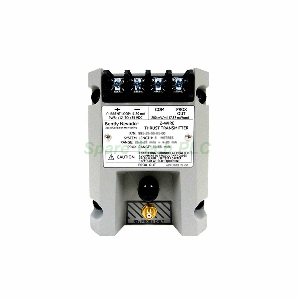
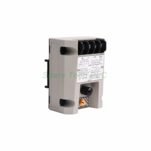
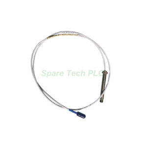
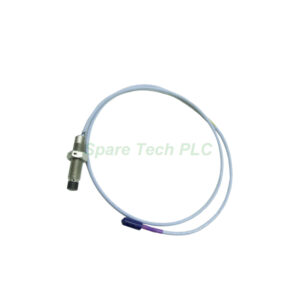
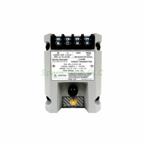
991 Thrust Transmitter 991-25-70-03-CN
Product Introduction
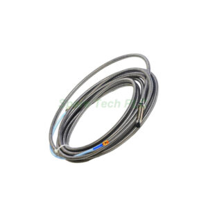
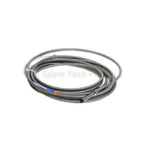
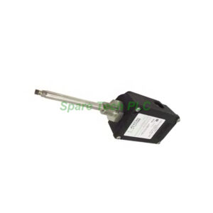
The Bently Nevada 991-25-70-03-CN is a dedicated thrust transmitter that converts axial shaft position into a proportional 4-20 mA signal. This model features a full-scale range of 25-0-25 mils and a system length of 7.0 meters (23.0 feet) . It accepts input from one non-contacting 3300 NSv proximity probe and its matching extension cable. The transmitter uses a DIN rail mounting option with clips and screws, simplifying installation in standard control cabinets. Furthermore, it carries country-specific approvals (CN) for global use in non-hazardous and Zone 2/Div 2 areas. For precise thrust monitoring in turbines, compressors, and pumps, the 991-25-70-03-CN offers reliable performance with easy field calibration.
Power and Output Specifications
This transmitter requires a +12 to +35 Vdc power supply at its terminal block, making it versatile for various DC power sources. It generates a 4 to 20 mAdc signal over the full-scale range using a standard 2-wire configuration. The loop accuracy is rated within ±1.5% (typical) when measured from the TEST signal input across a 250 Ω load resistor. Moreover, the maximum loop resistance is 1,000 Ω including cable at 35 Vdc, and the current limiting is typically 23 mA. The zero and span adjustments are non-interacting external potentiometers, allowing independent calibration without cross-talk. This design ensures that field technicians can fine-tune the output quickly and accurately.
Linear Range and Probe Setup
The 991-25-70-03-CN provides a linear range from 0.25 to 1.65 mm for Prox Out signals, suitable for 0.6-0-0.6 mm or 25-0-25 mils current loop linear ranges. For proper operation, the connected 3300 NSv probe must be gapped within this linear region to achieve the specified full-scale output. The transmitter's frequency response covers common thrust monitoring needs, though specific dynamic performance depends on the probe and target characteristics. Additionally, the minimum target size is consistent with the 3300 NSv probe specifications. This configuration ensures accurate axial position measurement for machinery protection systems.
NOT OK and Environmental Ratings
A key safety feature is the NOT OK/signal defeat function. The output drops to less than 3.6 mA within 100 µs after a NOT OK condition occurs, providing immediate fault indication to the control system. Once the condition clears, the signal restores within 0.1 seconds , significantly faster than many competing transmitters. The operating temperature ranges from -35°C to +85°C , while storage temperature spans -51°C to +100°C , ensuring reliable performance in harsh industrial environments. Furthermore, the unit is approved for non-hazardous, Zone 2, or Division 2 hazardous locations when powered at 28 V. Its rugged construction and country-specific approval (CN) make it suitable for international installations.
Installation and DIN Rail Mounting
Mounting the 991-25-70-03-CN is straightforward using the included DIN clips and screws (Mounting Option 03). First, snap the transmitter onto a standard 35 mm DIN rail and secure it with the provided screws for vibration resistance. Next, connect the 3300 NSv probe and extension cable to the input terminals, ensuring proper polarity. Then, wire the power supply (+12 to +35 Vdc) to the terminal block, observing the correct connections. For the 4-20 mA loop, keep total resistance below 1,000 Ω at 35 Vdc to maintain accuracy. Finally, adjust the zero and span potentiometers using a small screwdriver while monitoring the output with a multimeter. The non-interacting design simplifies this process significantly.
Packaging and Shipping
Each 991-25-70-03-CN unit is packaged in anti-static foam inside a corrugated carton for maximum protection. The package contains the transmitter assembly, DIN rail clips, mounting screws, and a wiring diagram for quick reference. The net weight is 0.43 kg (0.9 lbm) , and the gross weight including packaging is 0.68 kg. All shipments are dispatched via FedEx, UPS, or DHL with tracking numbers provided upon dispatch. Please note that calibration certificates and warranty documents are not included with this listing.
Frequently Asked Questions (FAQ)
1. Can I use this transmitter with probes other than the 3300 NSv?
No, the 991-25-70-03-CN is specifically calibrated for use with the 3300 NSv proximity probe and its extension cable.
2. What does the 25-0-25 mils range represent?
This range indicates a bi-directional measurement: 25 mils in one direction, zero at center, and 25 mils in the opposite direction for axial thrust monitoring.
3. How do I adjust the zero and span?
Use the two non-interacting external potentiometers on the transmitter face; adjusting one does not affect the other for easy calibration.
4. Is the 991-25-70-03-CN suitable for outdoor use?
Yes, its operating temperature range of -35°C to +85°C makes it suitable for many outdoor applications, but protect it from direct moisture.
5. What is the response time for the NOT OK function?
The output drops below 3.6 mA within 100 µs of a fault, and it restores within 0.1 seconds after the fault clears.