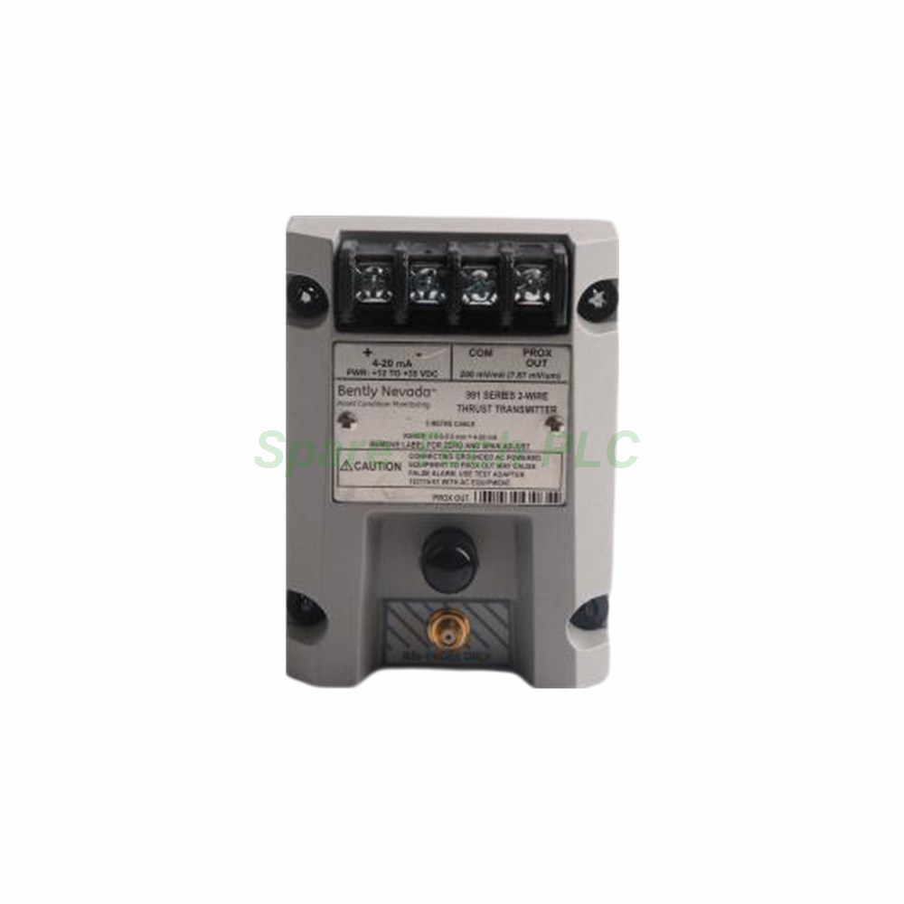
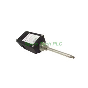
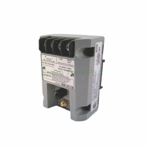
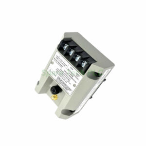
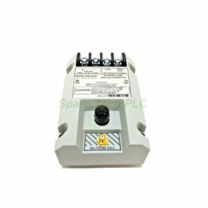
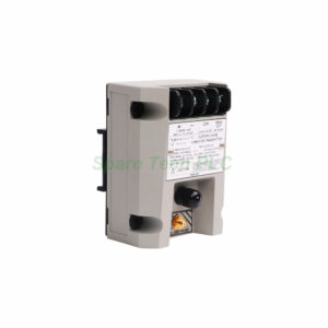
Bently Nevada 991-25-50-01-01 Thrust Vibration Transmitter
Product Introduction
This Bently Nevada transmitter converts proximity probe signals into a standard current loop. The 991-25-50-01-01 belongs to the 991 thrust transmitter family. It measures axial position on rotating machinery. Furthermore, the unit accepts one non-contacting 3300 NSv proximity probe and extension cable. The 25-0-25 mils full-scale range suits thrust bearing monitoring. Additionally, the DIN-rail clips simplify panel installation. The transmitter outputs a 4-20 mA signal in a 2-wire configuration. Therefore, plant engineers can feed the signal directly into a DCS or PLC. This device supports condition monitoring for steam turbines and compressors.
Technical Specifications
The 991-25-50-01-01 requires a +12 to +35 Vdc input at the transmitter terminal. The output covers 4 to 20 mAdc over the specified full-scale range. Loop accuracy stays within ±1.5% of full scale, typical. Maximum loop resistance reaches 1,000 Ω including cable at 35 Vdc. Current limiting sits at 23 mA typical. Zero and span adjustments are non-interacting and external. The linear range is 0.25 to 1.65 mm for Prox Out. Specifically, this suits 0.6-0-0.6 mm or 25-0-25 mils current loop linear ranges. The mounting option is 35 mm DIN-rail clips (code 01). The agency approval option is CSA Division 2 (code 01). The system length option is 5.0 meters (16.4 feet) (code 50).
Mechanical and Environmental Parameters
The transmitter operates from -35°C to +85°C (-31°F to +185°F). Storage temperature ranges from -51°C to +100°C (-60°F to +212°F). The unit weighs 0.43 kg (0.9 lbm). A Not OK condition drives the signal output below 3.6 mA within 100 µs. Signal output restores within 0.1 seconds after the Not OK condition clears. The 2-wire configuration reduces wiring cost. Besides, the DIN-rail mount saves cabinet space.
Installation Guide
First, mount the transmitter on a standard 35 mm DIN rail. Next, connect the 3300 NSv probe and extension cable to the input. Then, wire the 4-20 mA loop to your DCS or PLC. After that, apply +12 to +35 Vdc power at the transmitter terminal. Finally, adjust zero and span using the external controls. Keep loop resistance below 1,000 Ω at 35 Vdc. For instance, verify the TEST signal input against the voltage across a 250 Ω loop resistor. In hazardous areas, follow CSA Division 2 wiring rules. Moreover, route signal cable away from heavy electrical noise.
Packaging List
1 x Bently Nevada 991-25-50-01-01 Transmitter
1 x DIN-Rail Clip Set (pre-installed)
1 x Terminal Block Connector
1 x Installation Reference Sheet
FAQ
Q1: What input does this transmitter accept?
A: The 991-25-50-01-01 accepts one non-contacting 3300 NSv proximity probe and extension cable.
Q2: What is the output signal and power requirement?
A: It outputs 4-20 mA in a 2-wire configuration and requires +12 to +35 Vdc.
Q3: What is the full-scale range?
A: The full-scale option is 25-0-25 mils.
Q4: How is the unit mounted?
A: It mounts on 35 mm DIN-rail clips, option code 01.
Q5: What happens during a Not OK condition?
A: The output drops below 3.6 mA within 100 µs and restores within 0.1 seconds after the fault clears.