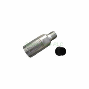
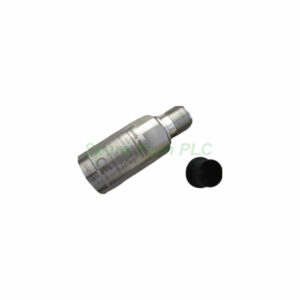
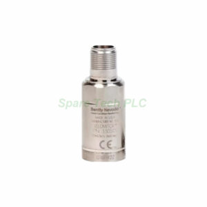
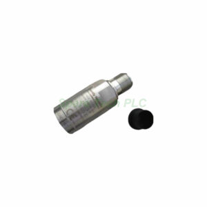
Bently Nevada 330500-00-00 Velomitor Product Introduction
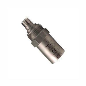
The Bently Nevada 330500-00-00 Velomitor provides direct velocity output without signal integration. This piezo-velocity sensor replaces traditional moving-coil velocity transducers. Its sensitivity reaches 3.94 mV/mm/s (100 mV/in/s) with a ±5% tolerance. Moreover, the velocity range extends to 1270 mm/s (50 in/s) peak.
This model comes with mounting thread option "-00", meaning no adapter is required. Agency approval option "-00" indicates that hazardous area certifications are not needed for this configuration. You can install the Bently Nevada 330500-00-00 in general-purpose industrial environments.
The case is electrically isolated from ground, which prevents ground loop issues. Additionally, the sensor uses a hermetically sealed 2-pin MIL-C-5015 connector with a 316L stainless steel shell. This construction ensures reliable operation in humid or corrosive conditions.
Technical Specifications of the 330500-00-00 Velomitor
Frequency Response and Accuracy
The Bently Nevada 330500-00-00 delivers a frequency response of 4.5 Hz to 5 kHz (270 to 300,000 cpm) at ±3.0 dB. For tighter tolerances, expect ±0.9 dB from 6.0 Hz to 2.5 kHz (360 to 150,000 cpm). Amplitude linearity stays within ±2% up to 152 mm/s (6 in/s) peak.
Output Characteristics
Output bias voltage measures -12 ±3.0 VDC over temperature, referenced to Pin A. Dynamic output impedance remains less than 2400 Ω. Consequently, the sensor drives long cable runs without signal degradation.
Noise Floor and Transverse Sensitivity
Broadband noise floor from 4.5 Hz to 5 kHz is only 0.004 mm/s (160 μin/s) rms nominal. Transverse sensitivity remains less than 5% of axial sensitivity. This low noise floor allows accurate measurements of small velocity changes.
Resonant Frequency
Mounted resonant frequency exceeds 12 kHz. This high resonance ensures the sensor avoids mechanical amplification within its normal 5 kHz operating range. Therefore, you get clean, reliable velocity data.
Temperature and Base Strain Effects
Temperature sensitivity typically varies from -14% to +7.5% over the full -55°C to 121°C range. Base strain sensitivity is 0.005 in/s/mstrain. The case isolated design further reduces external interference.
Mechanical and Environmental Parameters
Physical Dimensions and Weight
Weight without cable is typically 142 grams (5.0 oz). Diameter measures 25.3 mm (0.995 in). Height reaches 63.2 mm (2.49 in). Case material is 316L stainless steel, which provides excellent corrosion resistance.
Environmental Limits
Operating temperature ranges from -55°C to 121°C (-67°F to 250°F). Shock survivability peaks at 5,000 g. Relative humidity tolerance reaches 100% non-submerged because the case is hermetically sealed. Magnetic field susceptibility stays below 51 min/s/gauss at 50 gauss, 50-60 Hz.
Mounting Torque and Polarity
Apply a mounting torque of 32-46 kg-cm (24-40 in-lb) maximum. When the sensor case moves toward the connector, Pin A becomes positive with respect to Pin B. This polarity convention helps you verify correct wiring during installation.
Maximum Cable Length
You can extend the cable up to 305 metres (1,000 feet) using part number 02173006 without signal degradation. For applications with 50g vibration at 10 kHz and 200 pf/m cable capacitance, Bently Nevada recommends a maximum length of 63 metres (208 feet).
Compliance and Certifications for the 330500-00-00
The Bently Nevada 330500-00-00 complies with FCC Part 15 rules. It also meets EMC Directive 2014/30/EU and RoHS Directive 2011/65/EU. Furthermore, this sensor holds DNV certifications for:
Note on Hazardous Area Approvals
Although this specific "-00" option lacks agency approvals, the 330500 platform is available with Ex ia IIC T4 and Ex nL IIC T4 certifications for hazardous locations. For those versions, installation must follow drawing 167537 with T4 rating at -40°C to 100°C.
Installation Guidelines for the Bently Nevada 330500-00-00
First, prepare a flat mounting surface with a minimum 32 minch rms finish. Clean the threaded hole thoroughly. Next, apply anti-seize compound if operating in high temperatures. Then, screw the sensor into place by hand. Finally, tighten to 32-46 kg-cm (24-40 in-lb) using a calibrated torque wrench. Do not exceed this torque.
For optimal performance, avoid mounting on thin or flexible surfaces. Additionally, keep the sensor away from extreme magnetic fields exceeding 50 gauss. When routing the 2-pin MIL-C-5015 cable, use cable ties every 300 mm to prevent whipping. The case is isolated from ground, so you do not need isolation washers.
Polarity check: Verify that Pin A connects to the positive input of your monitoring system. The Bently Nevada 330500-00-00 produces positive voltage when the case moves toward the connector.
Packaging List
Bently Nevada 330500-00-00 Velomitor piezo-velocity sensor (1 unit)
Protective plastic dust cap for 2-pin MIL-C-5015 connector
Installation instruction sheet (1 copy)
Note: Certificates and warranty documents are not included in the package. Cables are sold separately.
Shipping Information
All orders ship via FedEx, UPS, or DHL with tracking numbers provided. Delivery typically takes 3-7 business days depending on destination.
Frequently Asked Questions (FAQ)
1. What is the difference between the 330500 Velomitor and a standard accelerometer?
The Bently Nevada 330500-00-00 outputs velocity directly without electronic integration. Accelerometers output acceleration, which requires integration to obtain velocity. Therefore, the Velomitor simplifies velocity monitoring applications.
2. Can I use the 330500-00-00 in hazardous areas?
No. This specific "-00" option has no agency approvals. However, Bently Nevada offers hazardous area versions of the 330500 with Ex ia IIC T4 or Ex nL IIC T4 certifications. Always verify your model number before installation.
3. What maximum cable length can I use without signal loss?
You can use up to 305 metres (1,000 feet) of Bently Nevada cable 02173006. For high-frequency applications (10 kHz, 50g vibration), Bently Nevada recommends 63 metres (208 feet) maximum with 200 pf/m cable capacitance.
4. How do I verify correct polarity during installation?
When the sensor case moves toward the connector, Pin A becomes positive with respect to Pin B. Connect Pin A to the positive input of your monitor. A simple tap test with an oscilloscope confirms polarity.
5. What happens if I exceed the mounting torque specification?
Exceeding 46 kg-cm (40 in-lb) may damage the sensor case or strip the mounting threads. Always use a torque wrench set to 32-46 kg-cm. Under-torquing can cause poor high-frequency response due to reduced mounting stiffness.