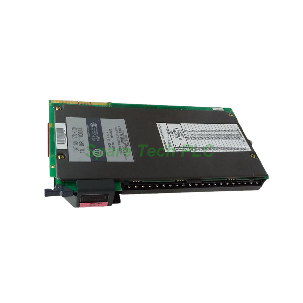
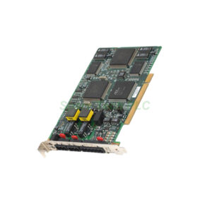
1771-IGD | Allen-Bradley 16-Channel Selectable Logic TTL Input Module
Product Introduction
The Allen‑Bradley 1771‑IGD is a versatile digital input module from the 1771 product family. It interfaces directly with TTL-compatible field devices, reading 5V DC signals from encoders, counters, and other high-speed digital sources. A standout feature is its selectable logic capability. You can choose between positive or negative logic states through a simple jumper setting. Consequently, this module adapts to various sensor types and control schemes. It delivers rapid response and robust protection, making it an excellent choice for demanding automation applications.
Technical Specifications
Input Characteristics
The 1771‑IGD module provides sixteen (16) input channels, all operating at 5 Volts DC TTL levels. The module offers exceptional flexibility through its selectable logic states. In positive logic mode, the module detects an ON state at 2.0 to 5.25V DC and an OFF state at -0.2 to 0.8V DC. In negative logic mode, these conditions reverse. Here, the ON state occurs at -0.2 to 0.8V DC and the OFF state at 2.0 to 5.25V DC. You can change this setting by repositioning a jumper toward the front of the module.
Power and Protection
This TTL input module draws a maximum backplane current of 130 mA at 5V DC. It also requires a customer-supplied 5V DC power source, with a total current rating of 380 mA per module. The acceptable supply voltage range is 5.0 to 5.3V DC, with a maximum ripple of 50 mV peak-to-peak. For protection, the module includes a 0.5A, 250V normal-blow fuse. This fuse safeguards the power supply and input terminals from voltage surges. Additionally, the module provides 1500V AC RMS isolation for one second, protecting the system from electrical transients.
Performance and Speed
The 1771‑IGD module excels in high-speed applications. The input signal delay measures less than 1 millisecond. This rapid response suits applications like position sensing, high-speed counting, and BCD interface decoding. The module has a maximum power dissipation of 2.7 Watts and a minimum of 0.4 Watts. Its thermal dissipation ranges from 1.4 BTU/hr to 9.2 BTU/hr. These figures indicate the module's efficiency and cooling requirements for your enclosure design.
Mechanical and Environmental Parameters
Environmental Ratings
The Allen‑Bradley 1771‑IGD operates reliably in standard industrial environments. It functions within a temperature range of 0 to 60 °C (32 to 131 °F). The module can withstand relative humidity levels from 5 to 95% non-condensing. Its shock resistance rating is 15 G while operating. For storage, the module handles temperatures from -40 to 85 °C. These ratings ensure stable performance across various factory floor conditions.
Status Indicators
The module's front panel features a comprehensive set of 18 LED status indicators. These include individual LEDs for each of the 16 input channels, providing visual confirmation of active signals. Additionally, a positive logic indicator and a module active indicator offer quick reference for the module's operational state. These LEDs simplify troubleshooting and system verification during startup and maintenance.
Installation and Configuration Guide
System Compatibility
The 1771‑IGD module is compatible with a broad range of 1771 chassis. It works with Series A or B versions of the 1771-A1B, 1771-A2B, 1771-A3B, 1771-A3B1, and 1771-A4B chassis. Additionally, it supports the 1771-AM1 and 1771-AM2 I/O chassis. This wide compatibility makes it a flexible choice for both new installations and system upgrades. Remember to configure the logic state jumper before installing the module.
Wiring with the 1771-WH Arm
This module requires the dedicated 1771‑WH wiring arm for all field signal terminations. This wiring arm enables quick module replacement without disconnecting individual field wires. For wiring, use 14 AWG stranded copper wire with an insulation rating of 60 °C. The maximum insulation thickness should not exceed 1.2 mm (3/64 inch). We recommend using Belden 8761 cable or an equivalent shielded cable. Apply a terminal screw torque of 1.0 Nm (9 lb-in) to ensure secure connections. Never connect AC voltage sources to any input terminal.
Packaging List
Your Allen‑Bradley 1771‑IGD order will include the following items:
Note: The module and its accessories ship in protective anti-static packaging to prevent ESD damage during transit. All orders ship via FedEx, UPS, or DHL.
Frequently Asked Questions (FAQ)
Q1: How do I switch the 1771-IGD between positive and negative logic?
You change the logic state by repositioning a jumper on the module. Move the jumper toward the front of the module to select negative logic. In its default position, the module operates in positive logic. Always set this jumper before installing the module.
Q2: What voltage range does the 1771‑IGD accept for an ON signal?
The acceptable ON voltage depends on your selected logic mode. For positive logic, ON occurs at 2.0 to 5.25V DC. For negative logic, ON occurs at -0.2 to 0.8V DC. Never apply AC voltage or voltages outside the specified TTL ranges.
Q3: Which chassis are compatible with the 1771‑IGD module?
This module works with many 1771 chassis. It supports Series A or B versions of the 1771-A1B, 1771-A2B, 1771-A3B, 1771-A3B1, and 1771-A4B. It also works with the 1771-AM1 and 1771-AM2 I/O chassis.
Q4: What is the signal delay for this input module?
The Allen‑Bradley 1771‑IGD offers a very fast response. The input signal delay is less than 1 millisecond. This speed makes it ideal for high-frequency TTL interfaces and BCD encoders.
Q5: What wiring arm does the 1771‑IGD require?
This module requires the 1771‑WH wiring arm. Use only this specific arm to ensure proper connections and maintain system integrity. The 1771-WH allows you to replace the module without disconnecting the field wiring.