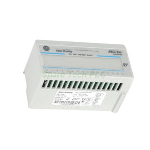
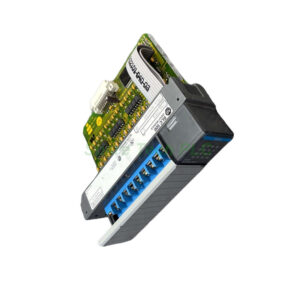
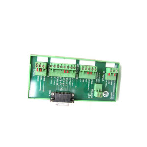
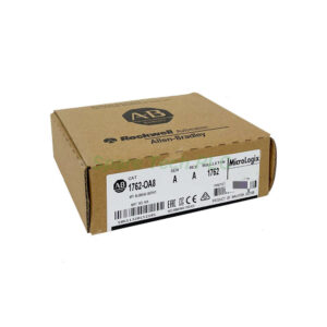
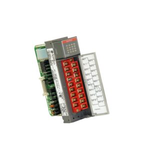
1746‑ITB16 Allen Bradley SLC 500 Fast Response Input Module
The 1746‑ITB16 from Allen‑Bradley is a high‑performance discrete input module designed specifically for the SLC 500 controller family. This module provides 16 sinking input channels that handle DC voltage signals from field devices such as proximity sensors, limit switches, and encoders. Its fast response capability sets it apart from standard input modules. Particularly, the 1746‑ITB16 achieves an ON‑state signal delay of just 0.3 ms and an OFF‑state delay of 0.5 ms, enabling precise capture of rapid switching events. Consequently, this module suits applications involving pulse counting, speed measurement, and position feedback. Moreover, when paired with an SLC 5/03 or SLC 5/04 processor, the 1746‑ITB16 supports discrete input interrupt (DII) instructions with 100 µs polling, reading pulse frequencies up to 1 kHz. Furthermore, using a gray code encoder like the Allen‑Bradley 845D series, the module can handle frequencies reaching 2 kHz. Therefore, the 1746‑ITB16 delivers reliable performance in demanding automation tasks, from packaging machinery to conveyor sorting systems.
Technical Specifications of the 1746‑ITB16
Understanding the electrical parameters ensures correct system integration. First, the 1746‑ITB16 operates across an input voltage range of 10–30V DC, with a nominal value of 24V DC. This wide window accommodates typical industrial power supply variations. The module employs a sink wiring configuration, which means the input common connects to the DC positive side, and field devices switch the negative side to ground. Each channel draws a nominal input current of 8 mA at 24V DC, providing sufficient energy for reliable state detection. Additionally, the maximum off‑state voltage is 5V DC, and the maximum off‑state current is 1.5 mA, ensuring a clean logic‑low signal. The backplane current consumption is rated at 0.085 A at 5V DC, which is relatively low and places minimal load on the chassis power supply. Furthermore, the module dissipates up to 3.6 W of power, so adequate ventilation within the enclosure is recommended.
Fast Response and High‑Speed Capabilities
The defining feature of the 1746‑ITB16 is its rapid response time. Specifically, the ON‑to‑OFF transition takes only 0.3 ms, while the OFF‑to‑ON transition completes within 0.5 ms under resistive loads. This speed makes the module suitable for capturing short‑duration pulses and high‑frequency signals. For instance, when monitoring a rotary encoder, the 1746‑ITB16 can track position changes with minimal latency. Moreover, the module integrates filter circuitry and optical coupling to reduce electrical noise, which is critical in environments with motors or variable‑frequency drives. Consequently, signal integrity remains high even in electrically noisy plant floors. Additionally, the module supports discrete input interrupt functionality, allowing the processor to respond immediately to critical events without scanning delays. Therefore, the 1746‑ITB16 excels in time‑critical applications such as emergency stops, high‑speed counting, and motion control feedback.
Installation and Wiring Guidelines
Proper installation maximizes the reliability and lifespan of the 1746‑ITB16. Begin by ensuring that power to the SLC 500 chassis is completely removed, as this module does not support removal under power (RIUP). Next, insert the module into any available slot of the 1746 chassis, applying firm, even pressure until the locking mechanism engages. The module directly connects to the backplane for power and communication. For wiring, use copper conductors with a gauge of 0.5 – 1.5 mm² (22–16 AWG). Strip approximately 7 mm of insulation and connect each field device to the corresponding input terminal. Remember that the 1746‑ITB16 uses sink wiring, so the common terminal should connect to the +V DC supply, while the field device switches the –V side. After wiring, verify all connections against the terminal layout diagram. Finally, apply power and observe the LED indicators – each channel has a dedicated status light that illuminates when the input is active. These LEDs simplify troubleshooting and field commissioning.
Mechanical and Environmental Parameters
The 1746‑ITB16 occupies a single slot in the SLC 500 chassis, saving valuable rack space for other modules. Its operating temperature range spans 0°C to 60°C (32–140°F), while storage conditions extend from -40°C to 85°C. Relative humidity tolerance is 5% to 95% non‑condensing, ensuring dependable operation in humid environments. The module meets industrial vibration and shock standards, so it withstands typical machinery oscillations. Additionally, the unit carries an open‑type enclosure rating, meaning it must be installed inside a suitable control cabinet to protect against dust and accidental contact. Therefore, always follow local electrical codes and panel layout recommendations when planning your installation.
Packaging List
1746‑ITB16 fast response input module (1 unit)
Removable terminal block (pre‑installed)
Slot filler cover
Installation instructions leaflet
Shipping via FedEx, UPS, or DHL – tracking number provided upon dispatch.
Frequently Asked Questions (FAQ)
1. Can the 1746‑ITB16 be used with any SLC 500 processor?
Yes, the 1746‑ITB16 is compatible with all SLC 500 fixed and modular processors. However, to leverage the discrete input interrupt and high‑speed polling features, you need an SLC 5/03 or higher processor.
2. What is the difference between sinking and sourcing wiring for the 1746‑ITB16?
The 1746‑ITB16 requires sinking wiring, meaning the common terminal connects to positive DC voltage, and the field device switches the negative side. If your sensors are sourcing outputs, you must use an interface relay or select a sourcing input module instead.
3. How do I connect a gray code encoder to the 1746‑ITB16?
Connect each encoder output channel to a separate input on the 1746‑ITB16. Ensure the encoder’s voltage matches the module’s 10–30V DC range. Allen‑Bradley recommends the 845D Absolute Gray Code Encoder for optimal compatibility and frequency response up to 2 kHz.
4. What should I do if an input channel does not respond?
First, check the LED indicator – a steady light confirms signal presence. If the LED remains off, verify the field device’s output voltage and wiring polarity. Also, test the input with a known good signal source. If the issue persists, inspect the backplane connection and cycle power to the chassis.
5. Are replacement terminal blocks available for the 1746‑ITB16?
Yes, you can order spare terminal blocks under part number 1746‑RTB (removable terminal block). This allows you to pre‑wire field devices and swap modules quickly without disconnecting individual wires, minimizing downtime during maintenance.