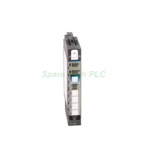
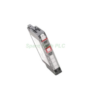
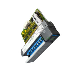
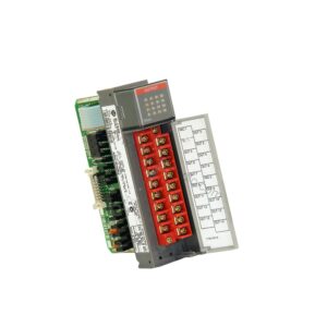
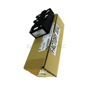
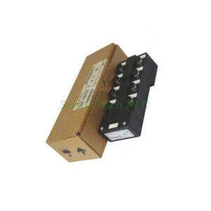
1734-IB4 4-Channel Sinking Input Module by Rockwell
Product Introduction
The Allen‑Bradley 1734‑IB4 belongs to the versatile POINT I/O family, which is well‑known for its compact form factor and cost‑effective distributed I/O solutions. This specific module provides four sinking input channels, making it an excellent choice for monitoring digital field devices such as proximity sensors, limit switches, and pushbuttons. It accepts a wide field power voltage range from 10 to 28.8V DC, with a nominal voltage of 24V DC.
Furthermore, the 1734‑IB4 integrates seamlessly with any POINT I/O communication adapter. This adapter supplies the POINTBus power and handles the network interface to the host controller. As a result, the module delivers reliable performance in demanding industrial environments while saving valuable panel space. Additionally, its intuitive front‑panel LEDs provide clear visual feedback for module, network, and channel status.
Technical Specifications
Focusing on its electrical characteristics, the 1734‑IB4 has a maximum on‑state current of 5 mA and a minimum on‑state current of 2 mA. Its nominal input impedance sits at 3.6 kΩ, while the maximum impedance reaches 4.7 kΩ. For off‑state conditions, the maximum voltage is 5V DC, and the minimum off‑state current is 1.5 mA. The module also features a user‑selectable input filter time ranging from 0.5 ms hardware up to 0...63 ms, which helps to debounce noisy signals.
For power consumption, the 1734‑IB4 draws 75 mA from the POINTBus at 5V DC. Its power dissipation is 1W, which translates to a thermal dissipation of 3.4 BTU/hour. Moreover, the module provides 50V continuous isolation voltage, ensuring protection between the field wiring and the internal logic.
Mechanical and Environmental Parameters
The 1734‑IB4 is built for industrial conditions. It has a compact footprint with dimensions of 56 x 12 x 75.5 mm (2.2 x 0.47 x 2.97 in.) and weighs approximately 31.8 g (1.12 oz). This lightweight design allows for high‑density mounting on a standard DIN rail. Importantly, the module carries an open‑style enclosure rating, so it must be installed inside a suitable cabinet.
Furthermore, the keyswitch position for this module is set to 1, which is a unique mechanical keying feature that prevents incorrect module insertion into the base. This careful design detail simplifies installation and reduces the risk of wiring errors.
Installation Guidelines
Proper installation of the 1734‑IB4 begins with selecting the correct DIN rail. Rockwell Automation recommends using zinc plate, yellow chromate steel DIN rail. Avoid using aluminum or plastic rails because they can corrode or oxidize, leading to poor conductivity and intermittent grounding issues.
Next, attach the DIN rail securely to the mounting surface. You should place anchors approximately every 200 mm (7.8 inches) to ensure stable support. After mounting the rail, simply snap the 1734‑IB4 onto it. All field wiring connections are made through the Removable Terminal Block (RTB) located at the bottom of the module. This RTB simplifies both installation and future maintenance.
Specifically, this module supports both two‑wire and three‑wire input signals. When wiring, remember that the 1734‑IB4 is a sinking input module. Therefore, the input devices must source current to the module. Finally, the I/O data generated by the module is mapped to the host controller via the communication adapter over the selected network, such as EtherNet/IP or ControlNet.
Packaging List
When you receive your Allen‑Bradley 1734‑IB4, the package includes the following items:
(1) 1734‑IB4 POINT I/O 4‑Channel Input Module
(1) Removable Terminal Block (RTB) for field wiring
(1) Installation Instructions manual
Please note that this product is shipped without certifications or warranty documentation.
Shipping Information
We ship all orders using reliable courier services. Your 1734‑IB4 will be dispatched via Fedex, UPS, or DHL to ensure fast and secure delivery to your location.
Frequently Asked Questions (FAQ)
1. What types of sensors work with the 1734‑IB4?
The 1734‑IB4 works with sourcing sensors like proximity switches, photoelectric sensors, and pushbuttons. It supports two‑wire and three‑wire DC devices.
2. Can I use the 1734‑IB4 with a 12V DC system?
Yes, it can. The field power voltage range of the 1734‑IB4 is 10 to 28.8V DC, which includes both 12V and 24V nominal systems.
3. How do I clear a fault on the 1734‑IB4 module?
First, check the module status LED. If it shows a recoverable fault, you can cycle power or reset the module via the communication adapter. For unrecoverable faults, inspect the wiring and replace the module if necessary.
4. What is the purpose of the keyswitch position on the 1734‑IB4?
The keyswitch position 1 mechanically prevents you from inserting the 1734‑IB4 into an incompatible base unit, thereby protecting both the module and the system from damage.
5. Is the 1734‑IB4 compatible with other POINT I/O modules?
Absolutely. The 1734‑IB4 is part of the POINT I/O family and works with any POINT I/O communication adapter and other POINTBlock modules for a scalable distributed I/O architecture.