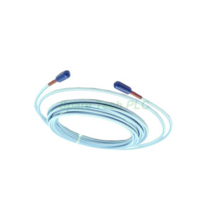
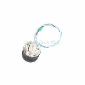
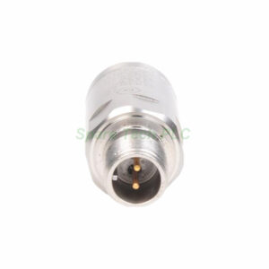
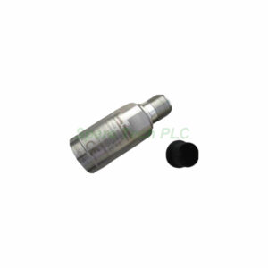
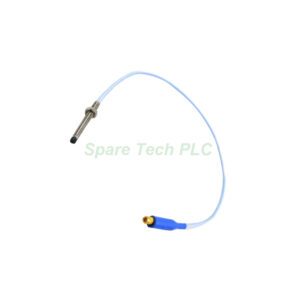
991 Thrust Transmitter Bently Nevada 991-25-70-03-00
Product Introduction
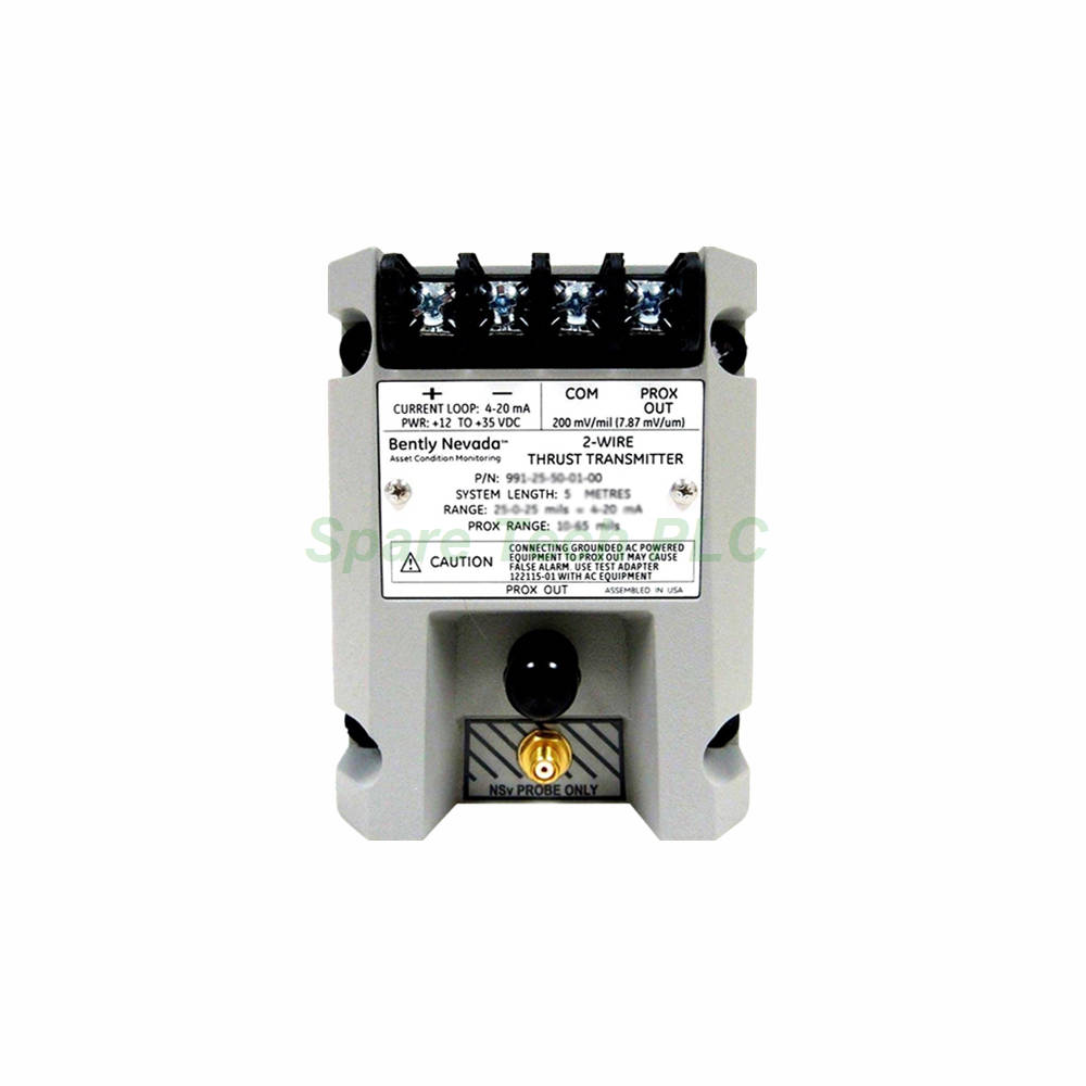
The Bently Nevada 991-25-70-03-00 is a dedicated 991 Thrust Transmitter engineered for axial thrust position measurement in rotating machinery. This transmitter accepts one non-contacting 3300 NSv Proximity Probe and extension cable. It converts the probe signal into a standard 4-20 mA output for seamless integration with control systems. The unit features a 25-0-25 mils full-scale range and a 7.0-meter system length. Moreover, the DIN rail mounting option with clips and screws simplifies installation in standard industrial cabinets. The transmitter includes non-interacting external zero and span adjustments, making calibration straightforward and efficient.
Technical Specifications
Electrical Parameters
The Bently Nevada 991-25-70-03-00 requires a +12 to +35 Vdc input at the transmitter terminal. Its 4-20 mA signal output operates in a 2-wire configuration across the specified full-scale range. The maximum loop resistance is 1,000 Ω including cable at 35 Vdc, while current limiting is typically 23 mA. The 4-20 mA loop accuracy stays within ±1.5% over the full-scale range (typical), rated from the TEST signal input to the voltage measured across a 250 Ω loop resistance.
Linear Range and Measurement
This thrust transmitter provides a linear range from 0.25 to 1.65 mm for the Prox Out signal. This range is suitable for 0.6-0-0.6 mm or 25-0-25 mils current loop linear ranges. The transmitter delivers precise axial position measurement for thrust bearing monitoring, enabling early detection of abnormal thrust movement.
NOT OK and Signal Defeat Features
The signal output drops to less than 3.6 mA within 100 µs after a Not OK condition occurs. Additionally, the signal restores within 0.1 seconds after the Not OK condition clears. This rapid response ensures your monitoring system immediately detects any sensor or wiring faults, while the quick recovery minimizes process disruptions.
Mechanical and Installation Parameters
Mounting and System Length
The 991-25-70-03-00 features DIN rail mounting with Option 03 (DIN clips and screws). This standard mounting method fits most industrial control cabinets and panels. The system length is 7.0 meters (23.0 feet), accommodating installations where the probe is located at a moderate distance from the transmitter.
Input and Probe Compatibility
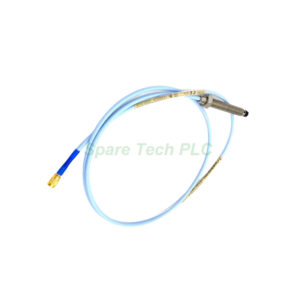
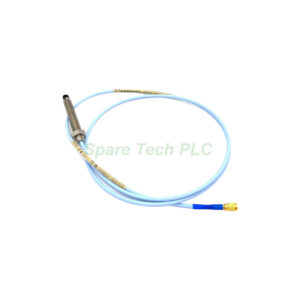
The input accepts one non-contacting 3300 NSv Proximity Probe and its matching extension cable. Always use Bently Nevada approved probes and cables to maintain specified accuracy and reliability. The transmitter weight is only 0.43 kg (0.9 lbm), making it lightweight and easy to handle during installation or replacement.
Environmental Limits
The transmitter operates reliably across a wide temperature range. The operating temperature spans from -35°C to +85°C (-31°F to +185°F). For storage, the temperature range extends from -51°C to +100°C (-60°F to +212°F). These ratings ensure the transmitter performs well in various industrial environments, including outdoor installations and harsh process areas.
Application and Use Cases
Axial Thrust Monitoring
This transmitter is specifically designed for axial thrust position measurement. It monitors the movement of a rotating shaft in the axial direction, which is critical for thrust bearing health. Excessive axial movement can indicate bearing wear, thrust loading issues, or process upsets. The Bently Nevada 991-25-70-03-00 provides continuous, real-time data for predictive maintenance and machine protection.
Compatibility with Control Systems
The 4-20 mA output interfaces directly with PLCs, DCS, and SCADA systems. This analog signal allows straightforward integration without additional signal conditioning. The 2-wire configuration reduces wiring costs and simplifies installation in existing systems.
Installation Guidelines
DIN Rail Mounting Procedure
First, secure the DIN rail clips and screws (supplied) to the back of the transmitter. Next, snap the transmitter onto the standard 35 mm DIN rail in your control cabinet. Ensure the clips engage firmly and the unit sits level. Subsequently, connect the 3300 NSv Proximity Probe and extension cable to the input terminals.
Wiring and Loop Connection
Connect the power supply (+12 to +35 Vdc) to the transmitter terminals. Wire the 4-20 mA output in a 2-wire loop configuration. Keep the total loop resistance below 1,000 Ω at 35 Vdc. Use twisted-pair shielded cable to minimize electromagnetic interference, especially in industrial environments with variable frequency drives or heavy electrical loads.
Probe Gap and Calibration
Gap the probe between 0.25 and 1.65 mm (10-65 mils) from the target to operate within the linear range. For the 25-0-25 mils full-scale configuration, set the probe at the midpoint of the linear range for best results. Use the external zero adjustment to set the 4 mA output at the desired zero position. Then, use the span adjustment to set the 20 mA output for the maximum thrust position. The non-interacting adjustments simplify the calibration process significantly.
Packaging List
1 x Bently Nevada 991-25-70-03-00 991 Thrust Transmitter
1 x DIN rail mounting kit (clips and screws)
1 x Terminal block connector
1 x Installation and calibration instruction sheet
Shipping Method: FedEx, UPS, DHL
Frequently Asked Questions
1. What is the full-scale range of the Bently Nevada 991-25-70-03-00?
The Bently Nevada 991-25-70-03-00 offers a 25-0-25 mils full-scale range. This chaotic range measures both positive and negative thrust positions relative to a set zero point.
2. What power supply does this thrust transmitter require?
This transmitter requires +12 to +35 Vdc input at the transmitter terminal. It operates on standard industrial DC power supplies commonly found in control cabinets.
3. How does the 991-25-70-03-00 mount in a control panel?
It mounts on a standard 35 mm DIN rail using the included DIN clips and screws (Option 03). This makes installation quick and tool-free in most industrial cabinets.
4. What probe is compatible with this transmitter?
The transmitter accepts one non-contacting 3300 NSv Proximity Probe and extension cable. Always use Bently Nevada probes for guaranteed performance and accuracy.
5. What is the response time when a Not OK condition occurs?
The signal output drops to less than 3.6 mA within 100 µs of a Not OK condition. The signal restores within 0.1 seconds after the condition clears, ensuring fast fault detection and recovery.