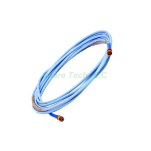
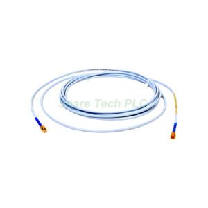
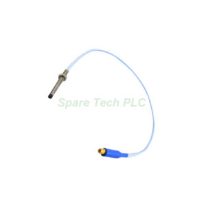
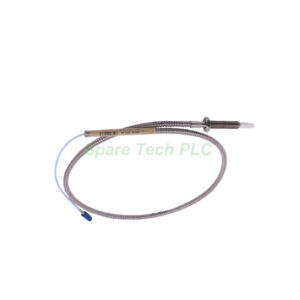
Bently Nevada 330500-07-04 Velomitor Piezo-velocity Sensor
Product Introduction
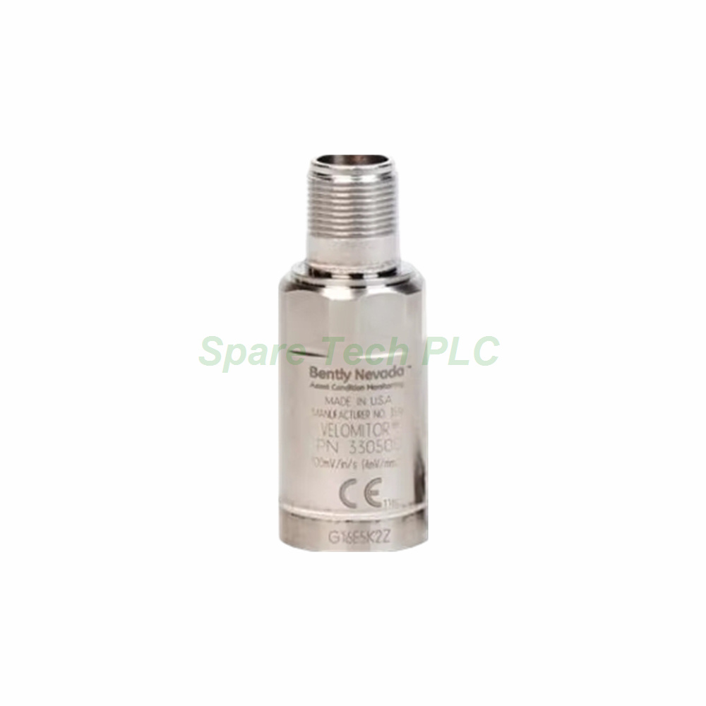
The 330500-07-04 is a versatile Velomitor piezo-velocity sensor from Bently Nevada, engineered for permanent vibration monitoring across a wide range of rotating equipment. This model distinguishes itself with a 3/8-16 UNC mounting thread, making it an excellent choice for installations where space constraints or smaller mounting pads exist. Furthermore, it carries multiple agency approvals including both CSA and ATEX, covering North American and European hazardous area requirements. The sensor outputs a direct velocity signal of 100 mV/in/s, simplifying integration with existing monitoring systems. Its hermetically-sealed 316L stainless steel housing provides robust protection against moisture and corrosion.
Core Electrical Performance
First, let us review the key electrical characteristics. The 330500-07-04 delivers a sensitivity of 3.94 mV/mm/s (100 mV/in/s) with a ±5% tolerance, ensuring consistent output across different units. Additionally, its frequency response spans 4.5 Hz to 5 kHz (270 to 300,000 cpm) within ±3.0 dB, with an even tighter ±0.9 dB window from 6.0 Hz to 2.5 kHz (360 to 150,000 cpm). Meanwhile, the velocity range extends to 1270 mm/s (50 in/s) peak, accommodating high-energy vibration events. The amplitude linearity remains within ±2% up to 152 mm/s (6 in/s) peak, which guarantees accurate representation of machine motion. The mounted resonant frequency exceeds 12 kHz, well above the typical measurement range.
Temperature Stability and Environmental Durability
Temperature fluctuations have a controlled impact on this sensor's performance. Specifically, the temperature sensitivity varies between -14% and +7.5% across the full operating range of -55°C to 121°C (-67°F to 250°F). This stability proves essential for outdoor installations or machinery with varying thermal conditions. Moreover, the 330500-07-04 can withstand shock loads up to 5,000 g peak, protecting it from sudden impacts during machine trips or start-ups. Its hermetically-sealed case allows operation in environments with up to 100% relative humidity, provided it remains non-submerged. Furthermore, the base strain sensitivity is only 0.005 in/s/mstrain, effectively minimising errors caused by mounting surface flexure.
Mechanical Design and Mounting Specifications
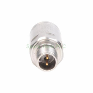
The sensor body has a diameter of 25.3 mm (0.995 in) and a height of 63.2 mm (2.49 in), with a typical weight of 142 grams (5.0 oz). Its case and connector shell are both fabricated from 316L stainless steel, offering superior resistance to pitting and corrosion in saline or chemical environments. The connector is a 2-pin Mil-C-5015 type, hermetically sealed to prevent moisture ingress. The mounting thread for this model is 3/8-16 UNC, indicated by the -07 suffix. Apply a mounting torque between 32-46 kg cm (24-40 in-lb) maximum to ensure proper mechanical coupling without overstressing the housing.
Signal Output and Cable Selection Guidelines
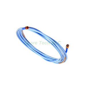
This sensor produces a dynamic output with an impedance of less than 2400 Ω. The output bias voltage is -12 ±3.0 VDC referenced to Pin A, and this value remains stable over temperature. Regarding polarity, when the case moves toward the connector, Pin A becomes positive relative to Pin B. For signal transmission, Bently Nevada recommends a maximum cable length of 305 metres (1,000 feet) using part number 02173006, with no signal degradation. For applications with high vibration levels (up to 50 g at 10 kHz) and cable capacitance of 200 pF/m, the recommended cable length is 208 feet (63 metres). Following these guidelines preserves signal integrity and measurement accuracy.
Hazardous Area Approvals and Global Compliance
The 330500-07-04 features the -04 agency approval option, which includes multiple certifications for global use. Specifically, it holds CSA and ATEX approvals for explosive atmospheres. It is rated Ex ia IIC T4 and AEx ia IIC T4 for Zone 0/1 installations, with a temperature class of T4 at ambient ranges from -40°C to 100°C. For Division 1 locations, it meets Class I, Groups A, B, C, D; Class II, Groups E, F, G; and Class III requirements. For Division 2, it carries Ex nL IIC T4 and AEx nA IIC T4 ratings. Additionally, this sensor complies with FCC Part 15, EMC Directive 2014/30/EU, RoHS Directive 2011/65/EU, and holds DNV marine and offshore certifications. Always install per drawing 167537 to maintain certification integrity.
Installation Best Practices for Optimal Performance
Proper installation ensures your 330500-07-04 delivers accurate vibration data over its service life. First, prepare a clean, flat mounting surface on the machine housing, free from burrs or paint. Next, apply a small amount of anti-seize compound to the 3/8-16 UNC threads to facilitate future removal. Then, tighten the sensor to the specified torque of 32-46 kg cm (24-40 in-lb) using a calibrated torque wrench. Avoid over-tightening, as this may stress the piezoelectric crystal inside. Additionally, route the cable away from high-voltage power lines and extreme heat sources to minimise electrical interference. Finally, connect the 2-pin Mil-C-5015 connector securely, ensuring proper pin alignment with your extension cable.
Packaging and Logistics Information
Every new 330500-07-04 sensor is shipped in original factory packaging, designed to protect the unit from shock and contamination during transit. The package contains the sensor assembly only; mounting hardware and cables are not included. We dispatch all orders using FedEx, UPS, or DHL, providing real-time tracking and reliable delivery to your facility. Please inspect the contents immediately upon receipt and report any shipping damage promptly.
Frequently Asked Questions (FAQ)
1. What is the main difference between the 330500-07-04 and the 330500-06-02?
The primary difference lies in the mounting thread. The 330500-07-04 uses a 3/8-16 UNC thread, while the 330500-06-02 uses 5/8-18 UNF. Additionally, the -04 model carries multiple approvals (CSA + ATEX), whereas the -02 has ATEX only.
2. Can I install this sensor on a horizontal pump bearing housing?
Yes, the 330500-07-04 is suitable for horizontal and vertical machine installations. Always mount it on a rigid, flat surface perpendicular to the measurement axis for best results.
3. What does the output bias voltage tell me about sensor health?
The bias voltage should measure -12 ±3.0 VDC between Pin A and Pin B at room temperature. A reading outside this range may indicate internal damage, connector issues, or cable faults.
4. Is the 330500-07-04 compatible with third-party vibration monitors?
Yes, as long as the monitor accepts a 100 mV/in/s velocity input with a bias voltage of -12 VDC. Always verify input impedance and power supply requirements before connection.
5. Does the multiple approval version cost more than the single-approval model?
Generally, the 330500-07-04 with CSA and ATEX approvals carries a premium over single-approval variants. This reflects the additional testing and certification processes involved.