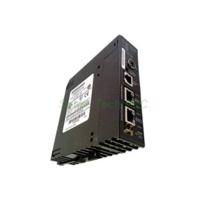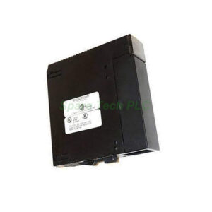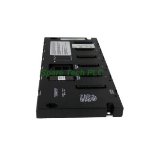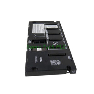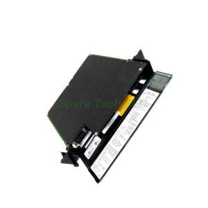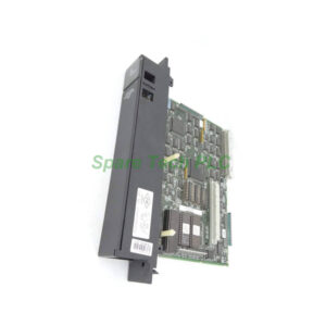
A06B-6058-H005 Replacement & Installation Manual for FANUC CNC
Product Introduction
The FANUC A06B-6058-H005 serves as the primary power input unit. It converts incoming AC power into the necessary DC bus voltage. This voltage powers the axis and spindle servo drives. This module includes a built-in charging circuit for the DC link capacitors. It also features a dynamic braking circuit for safe motor deceleration. Many FANUC systems rely on this module, including the popular 0i and 30i series. Consequently, understanding its functionality is crucial for any maintenance engineer.
Core Value
This module delivers high reliability in harsh industrial environments. Its primary value lies in the protection of expensive servo drives. The A06B-6058-H005 prevents overcurrent and overvoltage conditions. Furthermore, the regenerative circuit efficiently handles the energy returned from the motors. This design reduces heat generation inside the control cabinet. As a result, this component ensures stable machine tool accuracy and increases overall uptime.
Technical Insights
The A06B-6058-H005 uses a controlled rectifier design to manage the input current. Specifically, it employs a pre-charging sequence to limit inrush current. This process protects the main circuit breaker and the DC bus capacitors. The module sends a "Ready" signal to the CNC controller only when the DC voltage stabilizes. Additionally, the unit features LED indicators for immediate visual diagnostics. For instance, a red "ALM" LED signals a potential fault. This fault could be an overcurrent trip or a regenerative circuit failure. Therefore, engineers should always check these LEDs first during troubleshooting.
Installation & Maintenance
Always disconnect the main power before handling the A06B-6058-H005. Wait for the "Charge" lamp to fully turn off. This indicates the DC bus capacitors have completely discharged. Afterwards, you can safely remove the module. For installation, mount the unit on a clean, flat panel. Then, check all power terminals for proper torque. Loose connections can cause significant heat and damage. Moreover, ensure the cooling fan operates freely. Dust accumulation is a common failure point. We recommend cleaning the fan and internal heat sink every six months. Finally, verify the input voltage matches the module's rating, usually 200-240VAC.

Buyer’s Guide FAQ
Q: What are the signs of a failing FANUC A06B-6058-H005?
A: A sudden power loss during operation indicates a possible failure. Additionally, you may see a "Low Voltage" alarm (SV044) on the CNC screen. A loud buzz from the module often suggests a capacitor fault.
Q: Can I replace the A06B-6058-H005 with a different revision?
A: Yes, you typically can. However, check the FANUC design drawings for the specific revision compatibility. Later revisions often have improved components but remain electrically compatible.
Q: How do I test the FANUC A06B-6058-H005 module?
A: Start by measuring the DC bus voltage between terminals. It should read around 300VDC for a 230VAC input system. Also, check the 24VDC control supply output from the module.
Q: Why does the FANUC A06B-6058-H005 overheat?
A: Overheating usually occurs because of a blocked cooling fan. Also, ensure the ambient cabinet temperature stays below the 45°C specification. Check the load on the regenerative resistor as well.
Q: Is the FANUC A06B-6058-H005 a power supply or an amplifier?
A: This unit is the primary power supply module. It provides the DC power needed by the separate servo amplifier units. It also houses the main disconnect relay for the circuit.