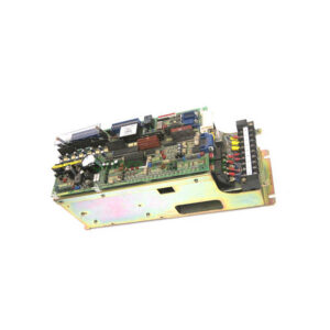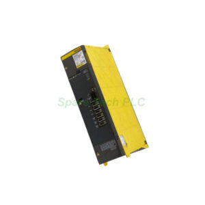
Allen‑Bradley 1791‑16A0 Block I/O Module: Installation & Maintenance Guide
Product Introduction
The Allen-Bradley 1791-16A0 belongs to the 1791 block I/O series. This module provides 16 discrete input channels. Each channel accepts 24V DC sink/source signals. Furthermore, the 1791-16A0 integrates optical isolation for each input point. This design protects the backplane from electrical noise. You can mount the module directly on machinery. Specifically, the 1791-16A0 eliminates separate I/O chassis. Consequently, it lowers total system costs for small to mid-size applications.
Core Value
This module simplifies distributed control architectures. Firstly, the Allen-Bradley 1791-16A0 reduces wiring efforts through one connector. Secondly, its compact size saves valuable cabinet space. Thirdly, you get faster installation compared to rack-based I/O. Moreover, the 1791-16A0 supports easy troubleshooting with LED indicators. Each input point has a status LED. Therefore, maintenance teams identify field device issues quickly. You also achieve higher system uptime with this reliable module.
Technical Insights
The Allen-Bradley 1791-16A0 operates at 24V DC nominal voltage. Input current is 7 mA per point at rated voltage. Additionally, the module offers 3 ms typical response time. This speed works for most discrete sensors. Specifically, the 1791-16A0 includes backplane current draw of 130 mA at 5V DC. Isolation voltage reaches 1500V AC between field side and logic. Meanwhile, the operating temperature ranges from 0°C to 60°C. You can store the module between -40°C and 85°C. Besides this, the 1791-16A0 meets NEMA standard enclosure type 1.

Installation & Maintenance
Follow these steps for the Allen-Bradley 1791-16A0. Firstly, disconnect system power before installation. Then mount the module on a DIN rail or directly on a panel. Use the built-in mounting holes. Next, connect field wiring to the removable terminal block. Verify each wire follows the label diagram. After wiring, set the node address using DIP switches. Furthermore, connect the communication cable to the block I/O bus. Apply power and check the status LED. A steady green indicates normal operation. For maintenance, regularly inspect the 1791-16A0 for loose connections. Clean dust from vents every six months. Also, test each input point annually with a known good sensor.
Buyer’s Guide FAQ
Q1: What is the Allen-Bradley 1791-16A0 used for?
A1: The 1791-16A0 collects 24V DC discrete signals from sensors and pushbuttons. It works with PLC systems as distributed I/O for conveyor systems, packaging machines, and assembly stations.
Q2: What is the difference between sink and source for the 1791-16A0?
A2: The 1791-16A0 accepts both sink and source inputs. Sink mode connects the load between input and +24V. Source mode connects the load between input and 0V. This flexibility matches various sensor types.
Q3: How do I set the node address on the 1791-16A0?
A3: Locate the DIP switch block on the module side. Set switches 1 through 6 for binary address values. Switch 7 is for baud rate selection. Always cycle power after changing the 1791-16A0 address settings.
Q4: Can I hot-swap the Allen-Bradley 1791-16A0?
A4: No, the 1791-16A0 does not support hot swapping. Always remove system power before inserting or removing the module. Failure to do so may damage the I/O bus or the module itself.
Q5: What LED indicators are on the 1791-16A0?
A5: The module has one green power LED and 16 amber input status LEDs. Each input LED lights when the corresponding field device is active. Additionally, a red fault LED indicates internal errors.