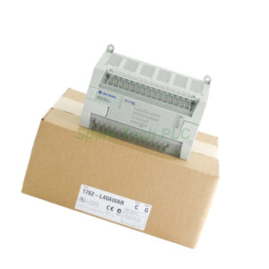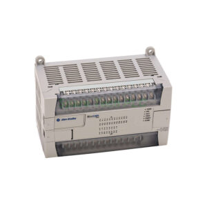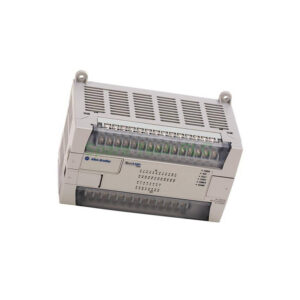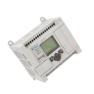
Allen‑Bradley 1791-0B32 Industrial I/O: Installation Guide
Product Introduction
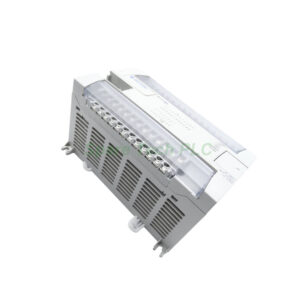
The Allen‑Bradley 1791-0B32 offers 32 digital input channels. Each channel accepts 24V DC sink/source signals. This block also provides built-in isolation. Specifically, the inputs share a common return path. The housing meets NEMA 1 standards. Therefore, you can install it in control cabinets without extra shielding. Moreover, the Allen‑Bradley 1791-0B32 uses removable terminal blocks. These blocks simplify wiring and board replacement. An LED indicator on each channel shows real-time status. This feature helps you troubleshoot field devices quickly.
Core Value
Why integrate the Allen‑Bradley 1791-0B32? Firstly, it lowers wiring labor. You place the block near field devices instead of pulling long cables back to a central rack. Secondly, it improves scan times. Local I/O processing reduces backplane traffic. Thirdly, it increases system flexibility. You can add or move blocks without reprogramming the entire PLC. Besides, the Allen‑Bradley 1791-0B32 works with any 1771 or 1794 adapter. It communicates via DeviceNet or remote I/O protocols. Specifically, this block supports autobaud detection. Therefore, integration takes minutes, not hours.
Technical Insights
The Allen‑Bradley 1791-0B32 operates from 24V DC nominal. It draws 200 mA maximum from the backplane. Input voltage ranges from 10V to 30V DC. Turn-on threshold sits at 10V; turn-off sits at 4V. Each channel provides optical isolation at 500V AC. Response times measure 5 ms for off-to-on and 10 ms for on-to-off. Moreover, the block features reverse polarity protection. This prevents damage during installation errors. Temperature ratings span 0°C to +60°C. The Allen‑Bradley 1791-0B32 also handles 5g vibration from 10 to 500 Hz. Use 20 AWG to 22 AWG stranded wire for connections.

Installation & Maintenance
Follow these steps for the Allen‑Bradley 1791-0B32. Firstly, mount the block on a DIN rail. Use the metal clip to secure it firmly. Secondly, connect the 24V DC power to the dedicated terminals. Thirdly, wire each field sensor to the numbered input points. Apply torque at 0.5 Nm for reliable contact. Next, set the node address using the rotary switches. For maintenance, perform quarterly visual checks. Look for loose wiring or LED anomalies. A solid red LED means no communication. Flashing green indicates normal operation. Clean the block with dry compressed air. Furthermore, keep a spare Allen‑Bradley 1791-0B32 on hand. Replace any block that shows intermittent readings.
Buyer’s Guide FAQ
1. What PLC systems work with the Allen‑Bradley 1791-0B32?
This block works with PLC-5, SLC 500, and ControlLogix via 1771 or 1794 adapters.
2. Can I replace the Allen‑Bradley 1791-0B32 without powering down?
No. You must power down the block before removing or inserting it.
3. What is the maximum cable length to the adapter?
For DeviceNet, keep cable runs under 500 meters. For RIO, stay under 300 meters.
4. Does the Allen‑Bradley 1791-0B32 support sinking or sourcing inputs?
It supports both. You connect the common terminal accordingly.
5. How do I confirm the revision of my Allen‑Bradley 1791-0B32?
Check the white label on the side. It shows the catalog number and revision code.