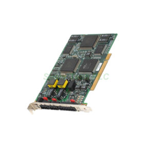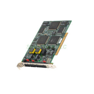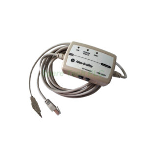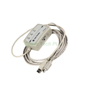
1734-APB PROFIBUS DP Slave Adapter Technical Installation & Setup Guide
Product Introduction
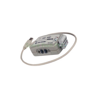
The Allen‑Bradley 1734‑APB acts as a PROFIBUS DP slave adapter. This module belongs to the Rockwell Automation POINT I/O family. It links digital and analog I/O modules to a higher‑level PROFIBUS network. The 1734‑APB handles all communication tasks efficiently. Specifically, it supports a baud rate up to 12 Mbps. Moreover, it supplies the backplane power to all connected I/O modules. You can mount it on a standard DIN rail. Therefore, this adapter simplifies system integration for distributed control architectures.
Core Value
Firstly, the 1734‑APB reduces complex wiring requirements. It uses a single PROFIBUS cable to transfer data from multiple sensors. Consequently, you save significant installation time and materials. Secondly, this module delivers robust diagnostic capabilities. It features built‑in status indicators for network and module health. These LEDs provide immediate visual feedback. Therefore, troubleshooting becomes faster and less intrusive. Furthermore, the hot‑swappable design allows module replacement without system shutdown. This feature minimizes production downtime. Meanwhile, the compact form factor saves valuable space within control cabinets.
Technical Insights
The 1734‑APB uses a D‑sub 9‑pin female connector for network access. It complies with the PROFIBUS DP‑V0 standard. This conformance ensures reliable cyclic data exchange with the master. Specifically, the adapter handles 64 bytes of input data and 64 bytes of output data. Moreover, you can configure the node address using a simple two‑position rotary switch. This physical addressing method avoids complex software preconfiguration. The module draws 5V DC from the system power supply. In addition, it provides galvanic isolation to protect against electrical noise. Therefore, you can operate this adapter reliably in harsh industrial environments.
Installation & Maintenance
Begin the installation by snapping the 1734‑APB onto the DIN rail. Ensure the rail is securely grounded before mounting. Next, attach the PROFIBUS cable to the 9‑pin connector. Verify the cable shielding is properly terminated. Then, set the node address using the rotary switches on the front face. Specifically, use a small screwdriver to set the tens and units digits. After addressing, apply power to the system. Check the module status LED for a steady green indication. For maintenance, regularly inspect the connector pins for corrosion. Additionally, verify the cable strain relief remains intact. Should a fault occur, replace the 1734‑APB with an identical unit. The system will automatically recognize the new module.

Buyer’s Guide FAQ
What is the primary function of the 1734‑APB?
This module functions as a PROFIBUS DP slave adapter. It connects your POINT I/O modules to a PROFIBUS fieldbus network.
What network standard does the 1734‑APB support?
The adapter fully supports the PROFIBUS DP‑V0 protocol. It communicates at speeds up to 12 Mbps.
Can I replace the 1734‑APB while the system is running?
Yes. The module supports hot‑swapping. You can remove and replace it without turning off the system power.
How do I set the address for the 1734‑APB?
Use the two‑position rotary switch located on the module face. Set the tens digit first and then the units digit.
What is the maximum data size for the 1734‑APB?
The adapter supports 64 bytes of input data and 64 bytes of output data per scan cycle.