STBDDI3725KS 16-Channel DC Input Module – Installation Guide
Product Introduction
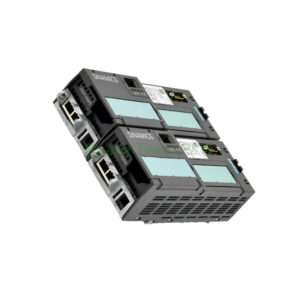
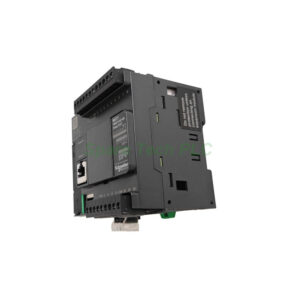
The Schneider Electric STBDDI3725KS digital input module offers sixteen channels of 24 Vdc discrete inputs for the Advantys STB system. Each channel on the STBDDI3725KS accepts both sink and source connections, matching various sensor types. This module operates with a nominal voltage range of 20.4 to 28.8 Vdc. The STBDDI3725KS draws its power directly from the STB bus, simplifying system wiring. Its compact form factor saves valuable cabinet space in distributed control architectures. The STBDDI3725KS integrates seamlessly with STB NIP and STB NCO adapters for fieldbus connectivity.
Core Value
The STBDDI3725KS delivers core value through its flexible input configuration and built-in diagnostic capabilities. Firstly, this module supports type 1 and type 3 input characteristics per IEC 61131-2 standards. Moreover, the STBDDI3725KS includes input filtering with adjustable response times to reject transient noise. Additionally, each input channel features LED status indicators for immediate visual verification. The STBDDI3725KS provides electrical isolation between the input channels and the bus, enhancing system immunity. This module also supports hot-swapping, enabling replacement without system shutdown.
Technical Insights
Understanding the input specifications of the STBDDI3725KS ensures correct application. Specifically, the module has a nominal input current of 5.5 mA per channel at 24 Vdc. The STBDDI3725KS guarantees ON-state recognition above 15 Vdc and OFF-state below 5 Vdc. Furthermore, this module offers a typical input delay of 3 ms, with software-configurable filtering up to 10 ms. The STBDDI3725KS consumes only 200 mA from the 5 Vdc logic supply. Its input impedance measures approximately 4.7 kΩ, allowing direct connection to 3-wire proximity sensors and pushbuttons.
Installation & Maintenance
Proper installation of the STBDDI3725KS ensures reliable field signal acquisition. Begin by mounting the module onto the STB distribution base using the provided clips. Then connect the 24 Vdc supply to the power input terminals. Route the field wiring to the removable screw terminal block for each input channel. Use twisted-pair shielded cables for runs longer than 30 meters. Maintain a separation of at least 10 mm between input wiring and high-power cables. For maintenance, periodically check the green and red LED indicators. A green LED on the STBDDI3725KS confirms proper bus communication. A red LED indicates an input overcurrent or power supply fault. Always disconnect power before removing or inserting the module.

Buyer's Guide FAQ
1. What is the input voltage range of the STBDDI3725KS?
The STBDDI3725KS accepts a nominal 24 Vdc input with a range of 20.4 to 28.8 Vdc, following IEC 61131-2 type 1 and type 3 standards.
2. Does the STBDDI3725KS support sink or source wiring?
The STBDDI3725KS supports both sink and source configurations. This feature provides maximum compatibility with various field sensors.
3. How many input channels does the STBDDI3725KS provide?
The STBDDI3725KS provides sixteen discrete input channels in a single module, offering high-density I/O for control cabinets.
4. Can I replace the STBDDI3725KS while the system runs?
Yes, the STBDDI3725KS supports hot-swapping. You can replace the module without powering down the entire Advantys STB system.
5. What causes a red fault LED on the STBDDI3725KS?
A red LED on the STBDDI3725KS typically indicates an input overcurrent or an internal power supply fault. Check the wiring and cycle the system power to clear the condition.