Woodward 5466-355 Remote Chassis Transceiver for VME Bus Systems
Product Introduction
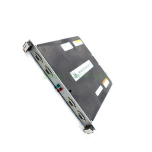
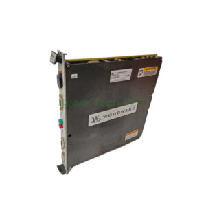
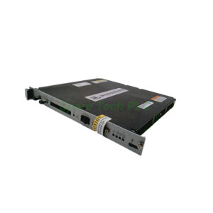
The 5466-355 from Woodward is a Remote Transceiver module. It works exclusively with CPU 68040 systems. This module must be installed in every remote I/O chassis. Each remote chassis connects to the main chassis via cable. The Woodward 5466-355 sends and receives control, data, and address information. Additionally, it connects directly to the chassis VME bus.
Technical Specifications
Interface and Communication Features
The system uses a parallel interface with high-speed differential line drivers. These drivers operate seamlessly at the VME transmission rate. Consequently, data transfer is both efficient and rapid. Signal degradation stays minimal, and electromagnetic interference is reduced.
Connector Design
Cable connectivity uses 100-pin metal shell Micro-D connectors. Two connectors are allocated for each 5466-355 module. This design ensures a robust and dependable connection. Moreover, it streamlines communication for better reliability.
Module Variants
Two versions of the Remote XCVR module exist. One version comes without termination resistors. The other version includes termination resistors. Your choice depends on chassis position in the expansion chain.
Functional Role
The Woodward 5466-355 acts as a bus receiver and driver. It communicates with the VME bus to exchange control, data, and address information. When the system needs to access this chassis, the chassis decoder activates the module. The receiver or driver then sends or receives information accordingly.
This module has no switches or LEDs. Therefore, troubleshooting relies on cable checks and systematic replacement. If the 5466-355 stops working, first inspect all cable connections. Second, replace the cables if problems persist. Third, replace the module itself if issues continue.
Installation Guidelines
Slot Requirement
The 5466-355 must be installed in Slot 1 of any remote I/O chassis. This rule applies to both versions of the module. Never install this module in any other slot.
Expansion Chassis Without Termination Resistors
For all expansion chassis except the last one in the chain, use the 5466-355 without termination resistors. Install this version in Slot 1. Additionally, each of these chassis requires a T-Module. Place the T-Module adjacent to the chassis. Use three-foot (0.9 m) cables to connect each expansion chassis to its T-Module.
Last Expansion Chassis With Termination Resistors
The final expansion chassis must use the 5466-355 that includes termination resistors. Install this version in Slot 1 as well. Termination resistors prevent signal distortion. They also manage signal reflections properly.
Cable Length Recommendations
Connections from the main chassis to the first T-Module need ten-foot (3 m) cables. Connections between T-Modules also use ten-foot cables. Finally, connections between the last T-Module and the final expansion chassis require ten-foot cables. Longer cables maintain signal integrity over increased distances.
Mechanical and Environmental Parameters
The Woodward 5466-355 shares the 9900 Series rugged design. Operating temperature ranges from 0°C to +60°C. Humidity tolerance is 5% to 95% non-condensing. The module resists vibration typical of turbine control rooms. Gross weight is only 1.8 kg, making installation easy.
Packaging List
Woodward 5466-355 Remote Chassis Transceiver (1 unit)
Two 100-pin Micro-D metal shell connectors (onboard)
Anti-static protective bag
Installation quick reference card
Note: No certificates or warranty documents are included in the package.
Shipping Information
We ship all orders via FedEx, UPS, or DHL. Worldwide delivery typically takes 3–7 business days. Tracking numbers are provided within 24 hours after dispatch.
Frequently Asked Questions (FAQ)
1. Can the 5466-355 work with non-Woodward CPU systems?
No, this Remote XCVR module only supports Woodward CPU 68040 systems.
2. How do I know which version of the 5466-355 to use?
Use the version without termination resistors for all expansion chassis except the last one. Use the termination resistor version only for the final expansion chassis.
3. What should I do if my remote chassis is not communicating?
First, check all cable connections on the 5466-355. Second, replace the cables. Third, replace the module if problems remain.
4. Why must this module be installed in Slot 1 only?
The VME bus architecture assigns specific addressing to Slot 1 for remote chassis communication. Other slots will not function correctly.
5. Can I mix cable lengths between chassis?
No, always use three-foot cables for T-Module connections and ten-foot cables for main-to-T-Module and inter-T-Module connections. Mixed lengths may cause signal reflection issues.