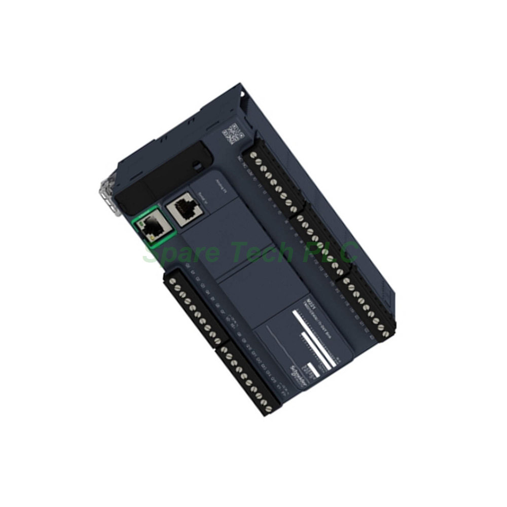
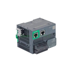
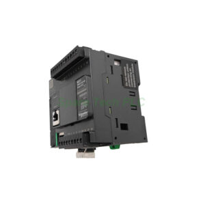
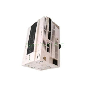
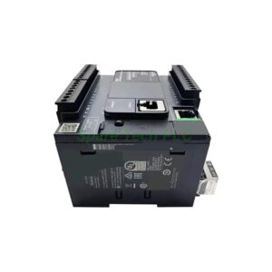
TM221CE40U – 24V DC PLC with NPN Transistor Outputs and Multi-Axis Motion
Product Introduction
The TM221CE40U belongs to the Modicon M221 series from Schneider Electric. This logic controller operates on a 24 V DC supply and provides 40 I/O points with NPN (sink) transistor outputs. What sets this model apart is its 4 fast outputs (Q0...Q3), which support PWM, PLS, and PTO (Pulse Train Output) functions at 100 kHz. This makes the TM221CE40U the ideal choice for multi-axis positioning, stepper motor control, and high-speed pulse generation. The controller also includes 4 fast counting inputs for encoder feedback. Furthermore, the built-in Ethernet port supports Modbus TCP and Ethernet/IP, enabling seamless integration with modern automation networks.
Technical Specifications
Power Supply and Inputs
The TM221CE40U runs on a 24 V DC supply with a range of 20.4 to 28.8 V. It consumes up to 17 W with a full expansion bus, or just 4.9 W without expansions. The power supply output delivers 0.52 A at 5 V and 0.3 A at 24 V for expansion modules. For discrete inputs, the unit offers 24 points that comply with IEC 61131-2 Type 1. These inputs support both sink and source wiring at 24 V DC. Among them, 4 inputs (I0, I1, I6, I7) are fast, with response times of just 5 µs. The controller also includes 2 analog inputs with a 0...10 V range and 10-bit resolution. Accuracy stays within ±1% of full scale.
Output Characteristics
This model features 16 NPN transistor outputs with negative (sink) logic. The outputs deliver 24 V DC at 0.5 A per channel, with a maximum of 4 A per common group. What makes this version unique is the 4 fast outputs (Q0...Q3) that support PWM, PLS, and PTO functions at 100 kHz. These outputs can generate pulse/direction or CW/CCW signals for up to 4 axes of motion. The remaining outputs (Q4...Q15) switch at 0.1 kHz for general-purpose control. Voltage drop stays below 1 V, and leakage current is only 0.1 mA. Mechanical durability exceeds 20 million cycles. However, note that these outputs do not include built-in overload or short-circuit protection, so external fusing is recommended.
Communication and Connectivity
The controller provides three communication ports. First, an Ethernet RJ45 port supports 10BASE-T/100BASE-TX with Modbus TCP server/client, Modbus TCP slave, and Ethernet/IP adapter. Second, a non-isolated serial link (RS232/RS485) handles Modbus RTU/ASCII. Third, a USB mini B port offers fast programming at 480 Mbit/s. These options give you flexible connectivity to HMIs, drives, SCADA, and programming software. Additionally, an SD card slot (2 GB max) supports data logging and program backup.
Memory, Performance, and Motion Functions
The controller stores programs in 256 kB of flash memory, handling up to 10,000 instructions. Execution time runs 0.3 ms per 1,000 instructions for periodic tasks, with Boolean instructions at 0.2 µs. The real-time clock drifts ≤30 s/month at 25 °C. For control loops, the unit supports up to 14 simultaneous PID regulators. Specifically for motion, the 4 fast outputs (Q0...Q3) generate PWM, PLS, or PTO signals at 100 kHz. You can configure them as:
PTO: 4 channels of pulse/direction or 2 channels of CW/CCW
PWM: Pulse width modulation for speed control
Frequency generator: Variable frequency output
Together with the 4 fast counting inputs (HSC mode) supporting A/B, single-phase, and pulse/direction modes, you can implement closed-loop positioning and encoder feedback for up to 4 axes without additional modules.
Mechanical and Environmental Specifications
Dimensions and Mounting
The TM221CE40U measures 160 mm wide, 90 mm high, and 70 mm deep. It weighs 0.78 kg. You can mount it on a DIN rail (TH35-7.5 or TH35-15) or secure it to a panel using the optional fixing kit. Note that this model is slightly taller (90 mm) compared to the CE40R and CE40T versions, so check your cabinet clearance accordingly.
Environmental Ratings
Operating temperature ranges from -10...55 °C for horizontal mounting, or -10...35 °C for vertical installation. Storage temperature spans -25...70 °C. Humidity tolerance is 10...95% without condensation. With the protective cover fitted, the unit achieves an IP20 rating. Vibration resistance is slightly lower than other M221 models at 1 gn (8.4...150 Hz) on both rail and panel mounting. Shock resistance is 147 m/s² (approx. 15 gn) for 11 ms.
Electrical Immunity
The TM221CE40U complies with EN/IEC 61131-2, EN/IEC 61010-2-201, and EN/IEC 60664-1 standards. It holds certifications including LR, CULus, CSA, EAC, DNV-GL, ABS, and RCM, making it suitable for marine and hazardous locations. It withstands ESD up to 8 kV in air and 4 kV on contact. Fast transients up to 2 kV on power lines are tolerated. Surge immunity reaches 2 kV common mode on AC power lines and 0.5 kV on DC power lines. Radiated and conducted emissions meet EN/IEC 55011 Class A limits.
Installation and Wiring Guide
Mounting Instructions
First, select a clean, flat surface within your control panel. For DIN rail mounting, snap the controller onto the rail until you hear a click. Verify the rail conforms to IEC 60715 (TH35-7.5 or TH35-15). For panel mounting, use the optional fixing kit. Maintain at least 50 mm clearance above and below for proper airflow. Keep the unit away from high-voltage or high-temperature components.
Wiring Recommendations
NPN transistor outputs require specific wiring. Use shielded cables for fast outputs (Q0...Q3) and keep lengths under 3 m to preserve signal integrity at 100 kHz. For standard outputs, unshielded cables up to 30 m work fine. For fast inputs, use shielded cables under 10 m; standard inputs accept unshielded cables up to 30 m. Analog inputs require unshielded cables under 1 m for best accuracy. The screw terminal blocks are removable for pre-wiring convenience. Connect the 24 V DC power supply (20.4...28.8 V) to the 3-terminal block. The sensor supply provides 24 V DC at 250 mA for external devices.
Important Protection Note
The TM221CE40U outputs do not include overload or short-circuit protection. You must add external fuses (0.5 A per channel recommended) or use protected drivers for each output. This is especially critical when driving inductive loads like relays, solenoids, or small motors. Add a flyback diode across each inductive load to suppress voltage spikes and protect the output transistors.
Grounding and Noise Suppression
Proper grounding is critical for transistor circuits. Connect the protective earth terminal to the panel ground with a low-impedance connection. Separate analog input wiring from digital and power lines to avoid interference. For fast outputs driving long cables, consider adding termination resistors to reduce reflections. Tie cable shields at the controller end only to prevent ground loops.
Packaging List
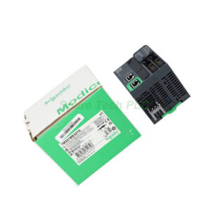
When you receive the TM221CE40U, the package includes the following items:
1 x TM221CE40U logic controller unit
1 x removable screw terminal block for inputs
1 x removable screw terminal block for outputs
1 x 3‑terminal block for 24 V DC power connection
1 x 4‑terminal block for analog inputs
1 x protective cover (pre-installed)
1 x quick start guide (printed)
Note: The SD card, programming cable (USB mini B), and DIN rail mounting accessories are sold separately. For shipping, we use FedEx, UPS, or DHL depending on your region.
Frequently Asked Questions (FAQ)
1. What makes the TM221CE40U different from the TM221CE40T?
Both use transistor outputs, but the CE40U has 4 fast outputs (Q0...Q3) at 100 kHz, while the CE40T has only 2 (Q0...Q1). The CE40U also uses NPN (sink) logic, whereas the CE40T uses PNP (source) logic. Additionally, the CE40U lacks built-in output protection, so external fusing is required.
2. Can I control 4 stepper motors with this controller?
Yes. The 4 fast outputs can generate PTO signals (pulse/direction) for up to 4 axes. Combine these with the 4 fast counting inputs for encoder feedback to implement closed-loop positioning.
3. Does this controller support Ethernet/IP?
Yes. The built-in Ethernet port supports Ethernet/IP adapter mode in addition to Modbus TCP server/client and Modbus TCP slave. This makes it compatible with Rockwell and other Ethernet/IP-based systems.
4. Why do the outputs have no protection? What should I do?
The outputs are unprotected to achieve faster switching speeds (5 µs response). You must add external 0.5 A fast-acting fuses per channel and use flyback diodes for inductive loads. This protects the transistors from overcurrent and voltage spikes.
5. What software do I need to program this PLC?
Use EcoStruxure Machine Expert – Basic (formerly SoMachine Basic). This free software supports the entire M221 series and offers ladder logic, function block diagram, and instruction list programming. The USB port provides a direct connection for fast downloads.