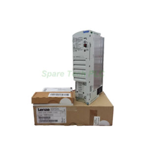
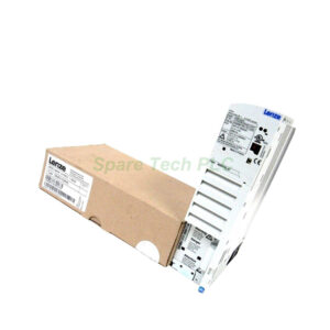
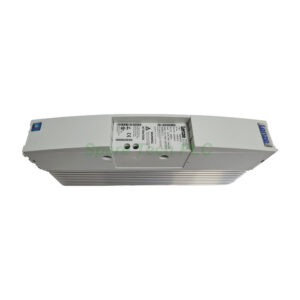
E82EV551K2C | Lenze 8200 Vector Drive 230V 0.55kW
Product Introduction
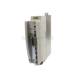
The Lenze E82EV551K2C belongs to the 8200 Series of frequency inverters. It functions as a base controller for small three-phase motors. With an output power of 0.55 kW (0.75 HP), this drive handles light-duty applications efficiently.
A key advantage of this model is its flexible input configuration. You can supply it with either single-phase or three-phase 230V AC. This flexibility makes the E82EV551K2C useful for retrofit projects where power availability varies.
Additionally, this inverter features vector control. Vector control gives you precise speed regulation and good torque at low frequencies. As a result, your equipment runs smoothly even under changing loads.
The built-in design mounts directly inside your control panel. Its low weight of only 1.2 kg simplifies installation.
Technical Specifications
Manufacturer: Lenze
Series: 8200
Part Number: E82EV551K2C
Product Type: Frequency inverter (base controller), vector controlled
Design Type: Built-in unit
Motor power (asynchronous, 4-pole): 0.55 kW
Output power equivalent: 0.75 HP
Mains voltage: 230V AC
Voltage phases: 1-phase or 3-phase
Built-in Brake Chopper
The E82EV551K2C includes an integrated brake chopper. This feature allows you to connect an external braking resistor. Regenerative energy from deceleration gets converted into heat.
Brake chopper data reference: 90 (refer to Lenze manual for exact resistance value)
For safe operation, always use a resistor that meets or exceeds the manufacturer's minimum resistance specification. A properly sized resistor prevents DC bus overvoltage faults during fast stops.
Environmental and Installation Data
Ambient operating temperature: –10°C to +55°C
Ambient storage temperature: –25°C to +60°C
Derating applies above 40°C. Reduce the output current by 2.5% per degree Celsius up to 55°C. For altitudes above 1000 meters, derate by 5% per additional 1000 meters.
Furthermore, the E82EV551K2C has a built-in design with IP20 protection. Therefore, you must install it inside a clean, dry control cabinet. Keep at least 50 mm clearance above and below for airflow.
Installation Guidelines
First, disconnect all power before handling the E82EV551K2C. Verify your mains voltage is 230V AC. For single-phase operation, connect live and neutral to the correct terminals. For three-phase, connect L1, L2, and L3.
Next, select the appropriate mains choke if needed. A choke reduces harmonic distortion and input current. Without a choke, the rated input current is higher as shown in the table above.
Then, connect your motor to the output terminals. Use a 3 A rated output current as a guide for cable sizing. For braking applications, wire an external resistor to the chopper terminals.
After wiring, configure the vector control parameters. Enter your motor's nameplate data for optimal torque performance. Finally, perform a low-speed test run before normal operation.
Packaging List
Note: Mains choke, braking resistor, and communication modules are not included. The package contains no certificate or warranty document.
Shipping
We ship worldwide using Fedex, UPS, or DHL. A tracking number will be provided after your order ships.
Frequently Asked Questions (FAQ)
1. Can the E82EV551K2C run on a standard 230V household outlet?
Yes, but only if your outlet supplies at least 6A. For single-phase operation, the drive draws 6A without a mains choke. Make sure your circuit breaker and wiring support this current.
2. What is the difference between E82EV551K2C and a three-phase only model?
The E82EV551K2C accepts both single-phase and three-phase input. Many other Lenze drives require three-phase power. This feature makes the 551 model more versatile for field upgrades.
3. Do I need a mains choke for this inverter?
Not always. Without a choke, the drive draws higher input current but still works fine. Use a choke if you have multiple drives on the same supply or if you need to meet harmonic limits.
4. What size braking resistor should I use with the E82EV551K2C?
Refer to the Lenze manual for the exact minimum resistance. The brake chopper data field shows "90" as a reference. A typical value is around 90 Ω. Always confirm with official documentation.
5. Why does the power loss show both 30W and 50W in different sources?
The 30W figure likely represents internal semiconductor losses. The 50W figure may include total losses under full load. For cabinet cooling calculations, use the higher 50W value to be safe.