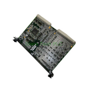
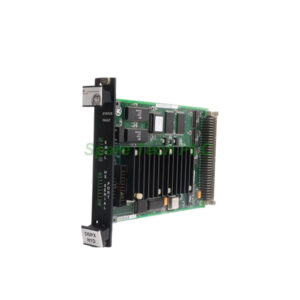
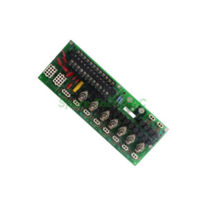
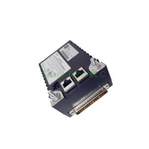
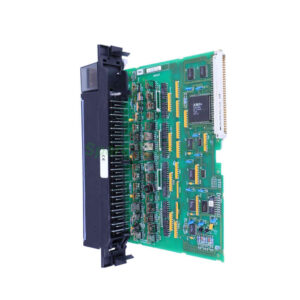
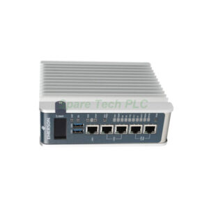
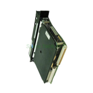
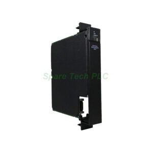
GE IS200EISBH1AAA Exciter ISBus Board
Product Introduction
The IS200EISBH1AAA serves as a dedicated communication board within the GE EX2100 excitation control system. This board connects the M1, M2, and C controllers through a proprietary GE interface called ISBus. Additionally, it receives and transmits fiber-optic feedback signals from the generator field.
Specifically, the IS200EISBH1AAA accepts current and voltage signals from EDCF boards. It also communicates with the Ground Detection module. For redundant exciter configurations, this board provides ISBus interface electronics. Therefore, reliable data transfer between controllers becomes possible even in fault scenarios.
Technical Specifications
Input & Signal Characteristics
Number of channels: 12
Input span: 4-20 mA
Common mode voltage range: ±5 V
Maximum lead resistance: 15Ω
Analog output current: 0-20 mA
Physical Attributes
Board height: 3U (single slot)
Dimensions: 8.26 cm high x 4.19 cm wide
Backplane connectors: One (P1)
Front panel: Six fiber-optic connectors, reset switch access opening, GE logo, board ID number
Component Population
Two transformers
One relay
One transistor
Multiple resistors, integrated circuits, and capacitors
Factory-drilled holes at each corner
Environmental & Compliance
Operating temperature: -30°C to 65°C
PCB coating: Conformal coating
Country of origin: United States
Manual: GEI-100454
Functional revision: A (first of three revisions)
Functional Description
Communication Architecture
The IS200EISBH1AAA acts as a communication interface between the DSPX boards located in M1, M2, and C controller positions. It receives fiber-optic feedback signals from the generator field. Then it transmits these signals over the control backplane to the DSPX controller. Furthermore, it enables RS-232C communication between the DSPX and both tool and keypad ports through the backbone connector.
ISBus Protocol
ISBus represents a GE proprietary communications interface. This board uses ISBus to transfer data among the M1, M2, and C controllers of the exciter. For redundant exciter systems, the IS200EISBH1AAA contains the necessary ISBus interface electronics. Consequently, seamless data exchange occurs even during controller failovers.
Fiber-Optic Signal Flow
The front panel houses six fiber-optic connectors. These connectors handle the following variable frequency signals:
Generator field DC voltage input (from EDCF board)
Generator field DC current input (from EDCF board)
Exciter voltage input (optional, from EDCF)
Exciter current input (optional, from EDCF)
Ground detector voltage input
Ground detector voltage output
Board Design and Installation
Physical Layout
The IS200EISBH1AAA uses a single-slot, 3U-high form factor. This board sits directly under the DSPX board in the control rack. The front faceplate includes a reset switch accessible through a dedicated opening. Six fiber-optic connectors populate another opening on the same faceplate.
Installation Procedure
First, power down the exciter rack completely. Next, locate the slot directly beneath the DSPX board. Align the IS200EISBH1AAA with the card guides. Push firmly until the single backplane connector (P1) seats properly. Then, connect all six fiber-optic cables to their respective ports. Finally, restore power and verify communication status.
Maintenance Considerations
The board's compact design simplifies replacement. Accessible mounting points and clear labeling aid troubleshooting. Factory-drilled holes at each corner provide additional mounting stability. The conformal coating protects against humidity and contamination.
Revision and Backward Compatibility
This board has undergone three total revisions. It remains backward-compatible with the first two revisions. Therefore, you can replace older versions with the IS200EISBH1AAA without system modifications. The functional revision A designation represents the current production standard.
Redundant System Applications
For redundant exciters, the IS200EISBH1AAA proves especially valuable. It contains ISBus interface electronics that maintain communication across all three controllers (M1, M2, and C). If one controller fails, the remaining controllers continue data exchange through this board. Consequently, system uptime improves significantly.
Packaging List
IS200EISBH1AAA Exciter ISBus Board (1 unit)
Anti-static shielded bag (1 piece)
Foam cushioning inserts
Fiber-optic port dust covers (6 pieces)
Quick reference card (port mapping and LED meanings)
Note: No cables, certificates, or warranty documents are included.
Shipping Information
We ship all orders via FedEx, UPS, or DHL. Standard delivery takes 3–7 business days. Orders placed before 3 PM ship the same day. Tracking numbers are provided within 24 hours after dispatch.
Frequently Asked Questions (FAQ)
1. Where does the IS200EISBH1AAA mount in the control rack?
This board mounts directly under the DSPX board. It occupies a single slot and uses a 3U height format. Do not install it in any other position.
2. What happens if a fiber-optic cable fails?
The affected signal path stops transmitting data. For example, generator field voltage feedback may be lost. Therefore, inspect all six fiber-optic connectors regularly. Keep spare cables on hand.
3. Can I use the IS200EISBH1AAA in a non-redundant exciter?
Yes, this board works in both simplex and redundant exciters. However, redundant configurations benefit most from its ISBus interface electronics. Simplex systems still require this board for basic communication.
4. How do I reset the board?
Access the reset switch through the opening on the front faceplate. Use a small non-conductive tool to press the switch. The board will reboot without needing rack power cycling.
5. What does the conformal coating protect against?
The coating protects the IS200EISBH1AAA from humidity, dust, and chemical vapors. It also prevents corrosion in non-climate-controlled environments. Therefore, this board lasts longer in turbine halls or outdoor cabinets.