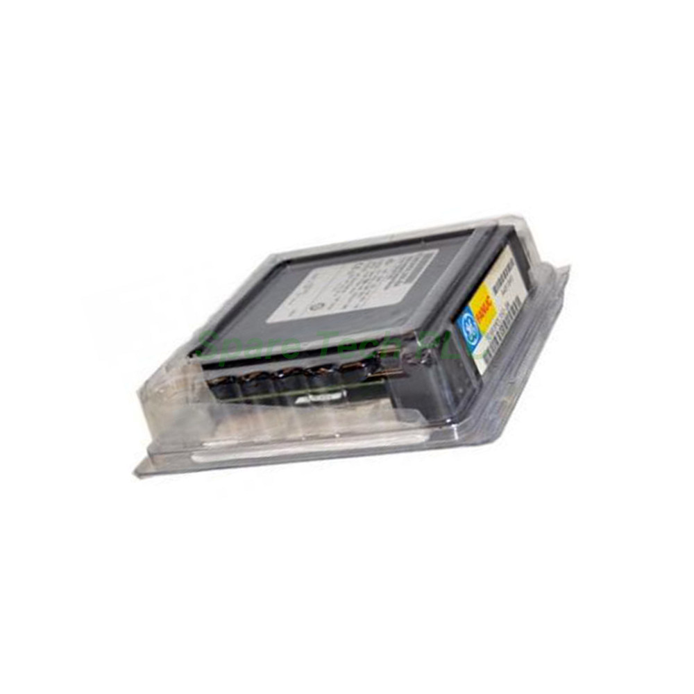
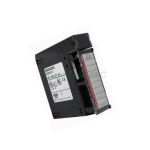
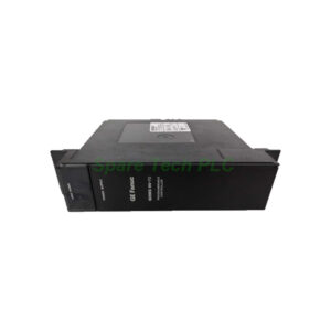
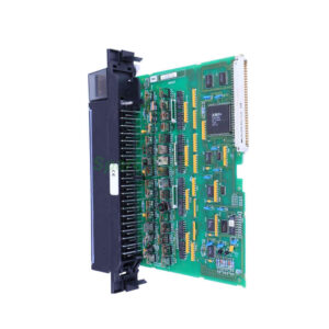
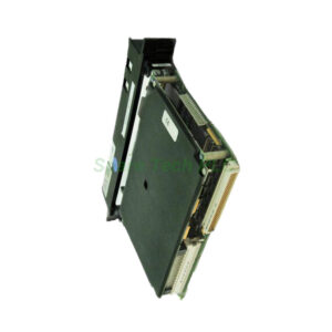
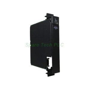
IC693MDL350 GE Fanuc Isolated Output Module Series 90-30
Product Introduction
The IC693MDL350 is an isolated output module manufactured by GE Fanuc for the Series 90-30 programmable logic controller platform. This module provides 16 isolated output points and operates on a nominal voltage range of 120 to 240 Volts AC, with an actual operating window of 74 to 265 V AC. Each point delivers 2 Amps of output current, making it suitable for driving a variety of field devices. Furthermore, the module features full isolation—both between field and backplane (250V AC continuous, 1500V AC for 1 minute) and between output groups—ensuring robust protection in industrial environments. A rear-mounted DIP switch allows users to configure the module's behavior when communication with the CPU is lost, offering either fail-safe shutdown or output hold. Additionally, LED indicators provide clear visual status for terminal block connection, simplifying troubleshooting and maintenance.
Technical Specifications
The IC693MDL350 delivers reliable AC output performance across a broad range of industrial applications. Below are the key technical parameters:
Nominal Output Voltage: 120 to 240 V AC
Output Voltage Range: 74 to 265 V AC
Frequency: 50 to 60 Hz
Number of Outputs: 16 isolated points
Output Current per Point: 2 A (max)
Minimum Load Current per Point: 10 mA
Maximum Inrush Current per Cycle: 20 A
Power Consumption: 315 mA at 5 V DC (bus)
Field to Backplane Isolation: 250 V AC continuous; 1500 V AC for 1 minute
Group to Group Isolation: 250 V AC continuous; 1500 V AC for 1 minute
DIP Switches: 2 (upper used for fail-safe mode selection)
LED Indicators: Terminal block presence (green = connected, red = removed)
Noise Immunity: High-level, reducing need for external snubbers
Additionally, the module's robust isolation ratings protect both the PLC backplane and connected field devices from voltage transients and fault conditions. This design enhances system reliability and reduces downtime.
Fail-Safe Configuration with DIP Switches
The IC693MDL350 includes two DIP switches on the rear of the module, although only the upper switch is used for configuration. This switch determines how the outputs respond when communication with the CPU is lost—a critical feature for safe system behavior during communication failures.
Specifically, when the switch is set to the right-hand position, all outputs turn off immediately upon loss of communication with the CPU. This fail-safe mode is typically preferred for safety-critical applications where de-energizing loads prevents hazardous conditions. Conversely, when the switch is in the left-hand position, the module maintains the last programmed output value. This mode suits processes where maintaining the last state is preferable to sudden shutdown.
Therefore, system designers can select the appropriate behavior based on their specific application requirements, adding flexibility to the control strategy.
LED Indicators and Status Monitoring
The IC693MDL350 features a unique LED indicator system that reports the status of the detachable terminal block. The indicator glows green when the terminal block is properly connected, confirming secure wiring. Conversely, it glows red when the terminal block is removed, providing an immediate visual alert during maintenance or troubleshooting.
This feature proves particularly useful in large systems with multiple I/O modules, as technicians can quickly identify modules with disconnected wiring without opening cabinets or using multimeters. Consequently, maintenance time is reduced and operational efficiency improves.
Noise Immunity and Load Compatibility
The IC693MDL350 offers high-level noise immunity, which protects the outputs against electrical noise commonly found in industrial environments. This built-in protection minimizes the need for external snubber circuits, reducing component count and simplifying installation.
Moreover, the module's outputs are well-suited for driving inductive loads (such as relays, solenoids, and contactors) as well as incandescent loads (such as indicator lamps). The 20A maximum inrush current per cycle accommodates the initial surge typical of these load types, ensuring reliable startup without nuisance tripping. For long-term operation, remember to use appropriate external fuses to prevent short-circuit damage, as recommended by GE Fanuc.
Installation Guidelines
Installing the IC693MDL350 is straightforward when following these steps:
Power Down – Disconnect power from the PLC rack before installation or removal.
Slot Selection – Choose an available I/O slot in the Series 90-30 chassis.
DIP Switch Setting – Set the upper DIP switch to the desired fail-safe position (right = off, left = hold).
Insertion – Slide the module along the card guides until it seats firmly into the backplane connector.
Wiring – Connect AC power and load wiring to the detachable terminal block using appropriate wire sizes and external fuses.
Terminal Block Attachment – Secure the terminal block to the module; verify the LED turns green.
Power Up – Restore power and monitor LED indicators for proper operation.
Additionally, ensure that external fuses are correctly rated for the connected loads to protect against overcurrent conditions. The detachable terminal block design simplifies wiring and replacement, as it can be removed without disconnecting individual wires.
Packaging List
Each IC693MDL350 unit includes:
One GE Fanuc IC693MDL350 isolated output module
One detachable terminal block (pre-attached)
Quick reference card (printed)
Note: No external fuses, wiring cables, programming software, or mounting hardware are supplied with the module.
Shipping and Logistics
All orders for the IC693MDL350 are shipped via trusted global carriers, including FedEx, UPS, and DHL. Each unit is carefully packaged to prevent damage during transit. Furthermore, tracking information is provided once the order is dispatched. Express delivery options are available for urgent requirements.
Frequently Asked Questions (FAQ)
1. What is the purpose of the DIP switch on the IC693MDL350?
The upper DIP switch determines the module's behavior when communication with the CPU is lost. In the right-hand position, outputs turn off (fail-safe). In the left-hand position, outputs maintain their last programmed value.
2. Can I use this module with DC loads?
No, the IC693MDL350 is designed exclusively for AC loads operating at 120 to 240V AC. It does not support DC output. For DC applications, consider other Series 90-30 output modules.
3. What do the LED indicators on this module show?
The LED indicates terminal block presence. It glows green when the terminal block is correctly connected and red when the terminal block is removed. This feature helps with quick visual inspection.
4. Does this module require external snubbers for inductive loads?
The IC693MDL350 provides high-level noise immunity, which generally eliminates the need for external snubbers. However, always verify compatibility with your specific inductive loads for optimal performance.
5. What is the maximum inrush current this module can handle?
The IC693MDL350 supports a maximum inrush current of 20 Amps per cycle. This capacity makes it suitable for loads with high startup surges, such as incandescent lamps and inductive devices.