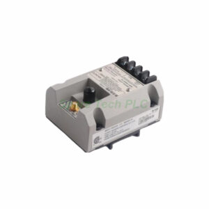
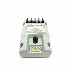
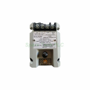
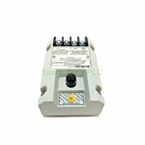
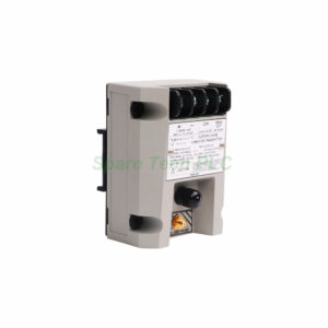
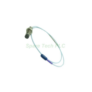
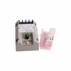
Bently Nevada 991-06-50-03-05 Probe Vibration Transmitter
Product Introduction
The Bently Nevada 991-06-50-03-05 is a reliable thrust transmitter from the 991 Series. It measures axial displacement in turbines, compressors, and other rotating machinery. This device works with a non-contacting 3300 NSv proximity probe. Moreover, it converts the probe signal into a standard 4-20 mA industrial current loop.
Specifically, the full-scale range is set to 0.6-0-0.6 mm. This makes it perfect for precise axial position monitoring. The system length option -50 provides a 5.0 meter (16.4 feet) cable. In addition, mounting option 03 includes DIN clips and screws for quick installation on standard rails.
Technical Specifications
Input and Power Requirements
The Bently Nevada 991 accepts one 3300 NSv proximity probe and its extension cable. Power requirements are +12 to +35 Vdc at the transmitter terminal. Therefore, it integrates easily with most 24 Vdc control systems.
Output Signal and Accuracy
This transmitter delivers a 4-20 mA output in a 2-wire configuration. The current loop linear range matches 0.6-0-0.6 mm or 25-0-25 mils. Typical loop accuracy is within ±1.5% of the full-scale range. Additionally, the maximum loop resistance reaches 1,000 Ω at 35 Vdc. Current limiting occurs at 23 mA typically.
Linear Range and Not OK Function
The linear range for proximity output is 0.25 to 1.65 mm. Zero and span adjustments are non-interacting and externally accessible. Meanwhile, the Not OK/Signal Defeat feature forces output below 3.6 mA within 100 µs. The output restores within 0.1 seconds after the Not OK condition clears.
Mechanical and Environmental Limits
Temperature Ratings
The transmitter operates from -35°C to +85°C (-31°F to +185°F). Storage temperature ranges from -51°C to +100°C (-60°F to +212°F). Consequently, this device performs reliably in harsh industrial environments.
Weight and Mounting
Weight is only 0.43 kg (0.9 lbm). Mounting uses DIN rail with included clips and screws. This method provides a secure and vibration-resistant installation.
Agency Approvals
Approval option 05 includes CSA Division 2, ATEX Zone 0, ATEX Zone 2, and ABS maritime approval. Thus, you can safely use this transmitter in hazardous locations and marine applications.
Installation Guidelines
First, mount the Bently Nevada 991-06-50-03-05 onto a standard DIN rail using the supplied clips and screws. Ensure the rail is securely fixed inside an appropriate enclosure. Next, connect the 3300 NSv proximity probe and extension cable to the input terminals.
Then, wire the 4-20 mA loop to a power supply providing between +12 and +35 Vdc. For instance, use a 250 Ω resistor to measure voltage across the loop for testing purposes. The TEST signal input allows easy verification of zero and span adjustments. Make sure the total loop resistance does not exceed 1,000 Ω. Finally, adjust the non-interacting zero and span pots to match the 0.6-0-0.6 mm range.
Packaging List
Bently Nevada 991-06-50-03-05 Probe Vibration Transmitter – 1 unit
DIN clips and screws (mounting option 03) – included
5.0 meter system length cable – pre-attached
Product manual – 1 copy
Note: Certificates and warranty documents are not included in this package.
Shipping
All orders ship via FedEx, UPS, or DHL. Tracking numbers are provided after dispatch.
Frequently Asked Questions (FAQ)
Q1: Which probe works with the Bently Nevada 991-06-50-03-05?
A1: It accepts one 3300 NSv non-contacting proximity probe and its extension cable.
Q2: What are the hazardous area approvals for this model?
A2: It has ATEX Zone 0, ATEX Zone 2, CSA Division 2, and ABS maritime approvals.
Q3: How does the Not OK function affect the output signal?
A3: The output drops below 3.6 mA within 100 µs and recovers within 0.1 seconds after the fault clears.
Q4: What is the maximum loop resistance allowed?
A4: The maximum is 1,000 Ω including all cable resistance at 35 Vdc input.
Q5: How do I adjust zero and span on this transmitter?
A5: Use the two external, non-interacting potentiometers located on the transmitter housing.