3500/22M-01-02-00 Bently Nevada Transient Data Interface
Product Introduction
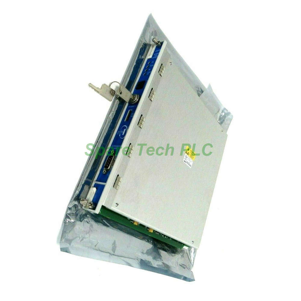
The Bently Nevada 3500/22M-01-02-00 serves as the essential communication bridge between the 3500 monitoring system and compatible host software. This Transient Data Interface combines the functionality of a 3500/20 Rack Interface Module (RIM) with the data collection capabilities of a dedicated communication processor. It resides in Slot 1, positioned adjacent to the power supplies in every 3500 rack. The 3500/22M interfaces with M series monitors to continuously gather both steady-state and transient dynamic waveform data. This information is then transmitted through an Ethernet link to System 1 Condition Monitoring software or 3500 System Configuration software. Static data capture comes standard, while dynamic and high-resolution transient data capture requires an optional Channel Enabling Disk.
Model Number Breakdown
Understanding the 3500/22M-01-02-00 configuration is straightforward. The base model is the 3500/22M Transient Data Interface. The -01 option specifies the Standard TDI type, suitable for standard monitoring applications. The -02 designation indicates the I/O Module Type is 100Base-FX Fiber Optic Ethernet. Finally, the -00 option means no agency approval option is included with this unit. This configuration provides high-speed fiber optic communication for installations requiring electrical isolation and extended cable runs.
Key Functions and Capabilities
The Bently Nevada 3500/22M-01-02-00 performs several critical functions within the 3500 rack. It collects static data continuously without requiring any additional hardware. Furthermore, it captures dynamic waveform data for up to 48 channels when the optional Channel Enabling Disk is installed. The TDI supports both synchronous and asynchronous data sampling across all operational modes. Importantly, while this module provides rack-wide communication functions, it does not participate in the critical monitoring path. Therefore, its operation has no effect on automatic machinery protection functions. Every 3500 rack requires exactly one TDI or RIM, and it must occupy Slot 1.
Waveform Sampling Capabilities
The 3500/22M-01-02-00 offers extensive waveform sampling flexibility. For synchronous sampling, users can select from multiple configurations: 1024 samples/rev for 2 revolutions, 720 samples/rev for 2 revolutions, 512 samples/rev for 4 revolutions, 360 samples/rev for 4 revolutions, or lower resolutions up to 16 samples/rev for 128 revolutions. Asynchronous data sampling supports an 800-line spectrum across frequency spans ranging from 10 Hz to 30 kHz. The asynchronous data is anti-alias filtered to ensure measurement accuracy. Channel pairs can be split among multiple monitors for orbit or synchronous full spectrum presentations, though asynchronous full spectrums require channels to be within a monitor channel pair.
Communication Interfaces
The 3500/22M-01-02-00 provides multiple communication options. The front panel includes a USB-B port supporting the BN Host Protocol at 115.2 kbaud maximum, with auto-baud capability. A 3-meter USB cable is included with the rack. The primary Ethernet interface is the 100Base-FX Fiber Optic I/O module. This supports full-duplex multimode fiber optic communication conforming to IEEE802.3u. It uses an MT-RJ Male connector, requiring a female connector on the fiber optic cable. Maximum cable length reaches 2000 meters (6560 feet), making it ideal for installations where the host computer is located far from the monitoring rack. The TDI supports both BN Host Protocol and BN TDI Protocol over Ethernet TCP/IP.
Front Panel Controls and Indicators
The front panel of the 3500/22M-01-02-00 includes several user controls and status indicators. The Rack Reset button clears latched alarms and Timed OK Channel Defeat, performing the same function as the Rack Reset contact on the I/O module. An Address switch sets the rack address, supporting up to 127 possible addresses. The Configuration Keylock places the rack in either RUN or PROGRAM mode. RUN mode enables normal operation while locking out configuration changes. PROGRAM mode allows both normal operation and remote or local configuration. The key can be removed in either position, providing flexibility for security management.
LED indicators on the front panel include the OK LED, which confirms proper module operation. The TX/RX LED indicates active communication with other modules in the rack. The TM LED illuminates when the rack is in Trip Multiply mode. The CONFIG OK LED confirms that the rack has a valid configuration loaded. Additionally, the I/O Module includes an OK Relay that indicates normal rack operation or fault detection. Users can select either OPEN or CLOSED contact to annunciate a NOT OK condition.
Power Consumption and Battery Life
The 3500/22M-01-02-00 consumes only 10.5 Watts of power during normal operation. An internal battery maintains configuration data and real-time clock settings. Under powered conditions at 50°C (122°F), the battery life extends to 38 years. When unpowered, the battery retains data for 12 years at the same temperature. This exceptional longevity ensures reliable configuration retention even during extended power outages or storage periods.
System Contacts and Signal Common
The I/O module provides several system contacts for external control. The Trip Multiply contact places the rack in Trip Multiply mode, with maximum current below 1 mAdc. The Alarm Inhibit contact inhibits all alarms in the rack. The Rack Reset contact clears latched alarms and Timed OK Channel Defeat. Both versions of the TDI I/O module include a 2-pin connector for connecting Signal Common to a single-point Instrument Ground. When connecting to ground, the selector switch on the Power Input Module (PIM) must be slid toward the "HP" arrow to isolate Signal Common from chassis ground.
Hazardous Area Approvals
The 3500/22M-01-02-00 carries multiple hazardous area certifications, enabling installation in potentially explosive environments. It is cNRTLus approved for Class I, Zone 2: AEx/Ex nA nC ic IIC T4 Gc and Class I, Division 2, Groups A, B, C, and D with T4 @ Ta = -20°C to +65°C. Additionally, it holds ATEX/IECEx certification for II 3 G Ex nA nC ic IIC T4 Gc and Ex ec nC ic IIC T4 Gc under the same temperature range. These approvals make the 3500/22M suitable for use in refineries, chemical plants, and other hazardous area applications.
Physical Specifications and Environmental Limits
The TDI module measures 241.3 mm x 24.4 mm x 241.8 mm (9.50 in x 0.96 in x 9.52 in) and weighs 0.91 kg (2.0 lbs). The associated I/O module is smaller at 241.3 mm x 24.4 mm x 99.1 mm (9.50 in x 0.96 in x 3.90 in) and weighs 0.20 kg (0.44 lbs). The TDI occupies one full-height front slot, while the I/O module uses one full-height rear slot.
Environmental operating temperatures range from -30°C to +65°C (-22°F to +149°F) for all components. Storage temperatures extend from -40°C to +85°C (-40°F to +185°F). The module supports humidity levels up to 95%, non-condensing.
Installation Guidelines
Installing the Bently Nevada 3500/22M-01-02-00 requires attention to slot positioning. First, ensure the rack is powered down completely. Next, identify Slot 1, which is located adjacent to the power supplies. Insert the TDI module into this front slot, ensuring firm engagement with the backplane connector. Then, install the I/O module in the corresponding rear slot. Secure both modules with their retaining screws. For fiber optic connections, use a cable with an MT-RJ Female connector to mate with the module's male connector. After power-up, verify that the OK LED illuminates and remains steady. Use the Configuration Keylock to set the desired operational mode.
Packaging List
Bently Nevada 3500/22M-01-02-00 TDI Main Module (1 unit)
100Base-FX Fiber Optic I/O Module (1 unit)
USB cable (3 meters)
Retaining screws (2 sets)
Configuration quick reference card
Frequently Asked Questions (FAQ)
1. What is the difference between the 3500/22M and the 3500/20 RIM?
The 3500/22M combines RIM functionality with communication processor capabilities, allowing direct data collection from M series monitors. The 3500/20 RIM provides only basic rack interface functions without dynamic data collection.
2. Can I use the 3500/22M-01-02-00 with copper Ethernet instead of fiber?
No, this specific version (-02) includes only the 100Base-FX fiber optic I/O module. For copper Ethernet (10Base-T/100Base-TX), choose the -01 I/O module option instead.
3. Does the TDI affect machinery protection functions?
No, the TDI is not part of the critical monitoring path. It has no effect on proper normal operation of the overall monitor system for automatic machinery protection. Protection functions continue independently even if the TDI experiences issues.
4. What software is compatible with this TDI?
The 3500/22M-01-02-00 communicates with System 1 Condition Monitoring and Diagnostic software, 3500 System Configuration software, 3500 Data Acquisition software, and 3500 Display software using BN Host and BN TDI protocols over TCP/IP.
5. How do I capture dynamic waveform data with this module?
Static data capture is standard. For dynamic and high-resolution transient data, you must install an optional Channel Enabling Disk. This unlocks the full 48-channel waveform collection capability.
6. What is the maximum fiber optic cable length for this module?
The 100Base-FX interface supports multimode fiber optic cable lengths up to 2000 meters (6560 feet), providing significant flexibility for remote host computer locations.
7. What shipping carriers do you use?
All orders ship via Fedex, UPS, or DHL with full tracking and insurance coverage for every shipment.