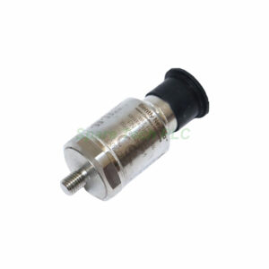
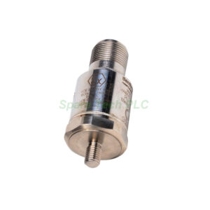
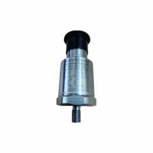
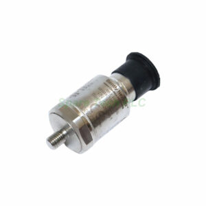
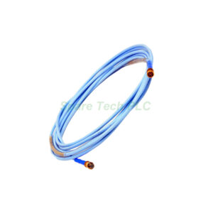
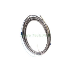
Bently Nevada 330500-08-02 Velomitor Piezo-velocity Sensor
Product Introduction
The Bently Nevada 330500-08-02 provides accurate velocity sensing for industrial vibration monitoring. This Velomitor Piezo-velocity Sensor converts case motion directly into a proportional electrical signal. You can use it in turbines, compressors, fans, and pumps.
Many facilities rely on Bently Nevada for machine protection. The 330500-08-02 model operates in extreme temperatures from -55°C to 121°C. Its 316L stainless steel case resists corrosion and seals against humidity. Additionally, the 1/2-13 UNC thread fits larger mounting holes commonly found in heavy machinery.
Technical Specifications
Electrical Sensitivity
The sensor provides 3.94 mV/mm/s (100 mV/in/s) ±5%. This output remains linear across the entire velocity range.
Frequency Response
From 4.5 Hz to 5 kHz (270 to 300 kcpm) at ±3.0 dB. Furthermore, the range of 6.0 Hz to 2.5 kHz (360 to 150 kcpm) keeps error within ±0.9 dB.
Output Bias Voltage
It outputs -12 ±3.0 VDC referenced to Pin A. This bias stays stable over the full temperature range.
Velocity and Linearity
Peak velocity reaches 1270 mm/s (50 in/s). Amplitude linearity remains within ±2% up to 152 mm/s (6 in/s) peak.
Transverse Sensitivity
Less than 5% of the main sensitivity. Therefore, side-to-side motion causes minimal measurement error.
Mounted Resonant Frequency
Greater than 12 kHz. This high resonant frequency prevents interference with your measurement band.
Dynamic Output Impedance
Below 2400 Ω. Thus, it can drive long cables without signal loss.
Broadband Noise Floor (4.5 Hz to 5 kHz)
Only 0.004 mm/s (160 μin/s) rms. This low noise floor ensures clean, reliable signals.
Grounding
The case is electrically isolated. Consequently, ground loops are much less likely to occur.
Maximum Cable Length
Up to 305 metres (1,000 feet) of cable part number 02173006. Signal degradation does not happen within this length.
Environmental and Mechanical Limits
Operating Temperature Range
-55°C to 121°C (-67°F to 250°F). Hence, it works for both cold startups and hot turbine areas.
Shock Survivability
Withstands 5,000 g peak. This rugged design prevents damage from sudden impacts or blade loss events.
Relative Humidity
Functions up to 100% non-submerged conditions. The hermetically-sealed case blocks all moisture ingress.
Base Strain Sensitivity
0.005 in/s/mstrain. Therefore, flexing of the mounting surface barely affects readings.
Magnetic Field Susceptibility
Below 51 min/s/gauss at 50 gauss, 50-60Hz. Thus, nearby motors or generators cause negligible interference.
Physical Dimensions
Weight is 142 grams (5.0 oz) typical. Diameter measures 25.3 mm (0.995 in). Height is 63.2 mm (2.49 in).
Case Material
316L stainless steel. This material offers excellent resistance to rust and chemical attack.
Connector
2-pin Mil-C-5015 with a 316L stainless steel shell. The connector is also hermetically sealed.
Mounting Torque
Apply 32-46 kg cm (24-40 in-lb) maximum. Over-torque may damage the sensor body or mounting threads.
Polarity
When the sensor case moves toward the connector, Pin A becomes positive relative to Pin B.
Recommended Cable Length for High Vibration
For 50g vibration at 10 kHz with 200 pF/m cable capacitance, use 63 metres (208 feet).
Compliance and Certifications
The 330500-08-02 meets several global standards. It follows FCC Part 15 rules. It also complies with EMC Directive 2014/30/EU and RoHS Directive 2011/65/EU.
Maritime approvals include DNV rules for ships, high-speed craft, and offshore standards.
Hazardous Area Approvals (-02 option)
Ex ia IIC T4 / AEx ia IIC T4
Class I, Division 1, Groups A, B, C, D
Class II, Groups E, F, G and Class III
Ex nL IIC T4 / AEx nA IIC T4
Class I, Div 2, Groups A, B, C, D
Temperature rating: T4 @ -40°C ≤ Ta ≤ 100°C. Install per drawing 167537. The -02 option specifically indicates ATEX (European) approval.
Installation Guide
First, clean the mounting surface thoroughly. Next, apply anti-seize compound on the 1/2-13 UNC threads if needed. Then, hand-tighten the 330500-08-02 sensor into place. Finally, torque it to 32-46 kg cm (24-40 in-lb) using a calibrated wrench. Avoid over-tightening.
Use a compatible cable such as part number 02173006. Connect Pin A and Pin B correctly by following the polarity rule above. If you extend cable beyond 63 metres in high-frequency environments, verify signal integrity first.
Route the cable away from high-voltage lines or variable frequency drives. This practice minimizes electrical noise pickup and ensures accurate readings.
Packaging List
Bently Nevada 330500-08-02 Velomitor Piezo-velocity Sensor (one unit)
Protective dust cap for the 2-pin Mil-C-5015 connector
Installation instruction sheet (drawing reference 167537)
Note: No calibration certificate or warranty document is included. Please contact us separately for those items.
FAQ
1. What is the difference between 330500-08-02 and 330500-04-04?
The 330500-08-02 has a 1/2-13 UNC mounting thread and ATEX approval (-02). The -04-04 version uses 1/4-20 UNC threads and multiple approvals including CSA. All electrical specifications remain identical.
2. Can I use the Bently Nevada 330500-08-02 in a Class I, Division 1 location?
Yes. This sensor carries Ex ia IIC T4 and Class I, Division 1, Groups A, B, C, D approvals. Always install per drawing 167537 for safety.
3. What happens if I exceed the 1270 mm/s peak velocity?
The output may clip or become non-linear. Above 152 mm/s, amplitude linearity exceeds ±2%. Consequently, measurement accuracy will decrease.
4. Does the 330500-08-02 work with existing Bently Nevada monitoring systems?
Yes. Most Bently Nevada monitors accept the Velomitor Piezo-velocity Sensor signal. Verify that your monitor accepts a -12 VDC bias and 3.94 mV/mm/s sensitivity.
5. What shipping methods do you offer for this sensor?
We ship worldwide via FedEx, UPS, or DHL. Delivery typically takes 3-7 business days depending on your location.
Attention: The above product information is sourced from the internet and cannot be guaranteed to be authentic.
For specific product parameters and prices, please contact
SpareTech PLC professionals in a timely manner.