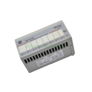
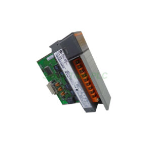
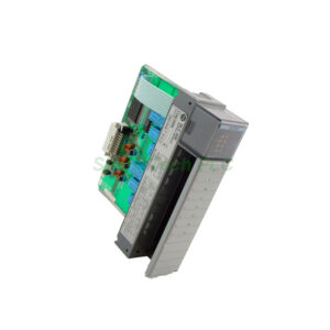
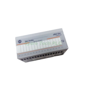
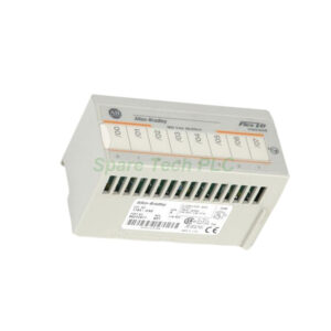
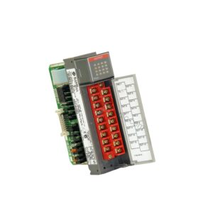
1794-IV32 Flex I/O 32-Point Digital Input Module
Product Introduction
The Allen‑Bradley 1794‑IV32 module offers a reliable interface for digital field devices in distributed I/O systems. This digital input module connects switches, sensors, and auxiliary contacts directly to your control network. It operates on a nominal 24V DC input voltage, which suits most common industrial applications. The module transfers data from its 32 channels through the FlexBus and a communication adapter to the host controller.
Technical Specifications
The 1794‑IV32 module exhibits stable electrical performance across its operating range. It accepts a nominal input of 24V DC, and its on‑state voltage spans from 19.2V DC to 31.2V DC. Typically, the on‑state current measures 4.1 mA at 24V DC, with a minimum of 2.0 mA and a maximum of 6.0 mA. Moreover, this module draws only 40 mA from the FlexBus at 5V DC.
For signal conditioning, the 1794‑IV32 provides multiple input filter times to suppress noise and contact bounce. You can choose from 0.25 ms, 0.5 ms, 1 ms, 2 ms, 4 ms, 8 ms, 16 ms, or 32 ms. The module defaults to 0.25 ms for fast response. Additionally, 32 yellow status LEDs, one per channel, give you clear visual feedback on each input's current state.
Mechanical and Environmental Parameters
The 1794‑IV32 mounts easily onto any 1794 series terminal base unit. It works seamlessly with the 1794‑TB32, 1794‑TB32S, 1794‑TB62DS, and 1794‑TB62EXD4X15 bases. A built‑in keyswitch ensures correct positioning, while a positive‑locking latch secures the module firmly in place.
This module operates reliably in indoor industrial environments only. It meets Pollution Degree 2 and Overvoltage Category II standards, and it functions properly at altitudes up to 6562 feet. When installed, the module measures 3.7 x 3.7 x 2.7 inches and weighs approximately 77 grams.
Installation Guidelines
Installing the 1794‑IV32 correctly guarantees trouble‑free operation. First, turn the keyswitch on the terminal base to position 2, the designated setting for this module. Next, slide the Flexbus connector fully to the left to link the module with the adjacent base or adapter.
Then, align the module's groove with the alignment bar on the terminal base. Press the module straight in until you hear the latch click into place. For wiring, connect each input wire to the numbered terminals (0‑31) on rows A and B. Also, wire the power and common terminals from row C (terminals 35‑51) according to your input grouping. Do not use terminals 16 or 33, as these remain unconnected.
Packaging List
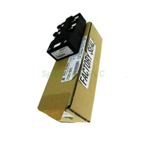
Your shipment for the 1794‑IV32 includes the following items:
Frequently Asked Questions (FAQ)
Q1: What field devices can I connect to the 1794‑IV32 module?
A1: This module accepts sourcing inputs, so you can connect push buttons, limit switches, proximity sensors, and auxiliary contacts that supply a 24V DC signal to the channel.
Q2: How do I choose the correct filter time for my application?
A2: For clean, fast signals, stick with the default 0.25 ms setting. For noisy environments or mechanical switches, select a longer filter time, such as 8 ms or 16 ms, to eliminate false triggers.
Q3: Which terminal base units work with the 1794-IV32?
A3: This module fits the 1794‑TB32, 1794‑TB32S, 1794‑TB62DS, and 1794‑TB62EXD4X15 bases. Choose the base that matches your wiring requirements.
Q4: What do the yellow LEDs on the front panel indicate?
A4: Each yellow LED corresponds to one input channel. The LED lights up when the channel receives a valid on‑state voltage from the connected device.
Q5: Can I install the 1794-IV32 outdoors or in hazardous areas?
A5: No, this module supports indoor use only. It is not suitable for hazardous locations and requires a clean, dry environment with Pollution Degree 2 or better.