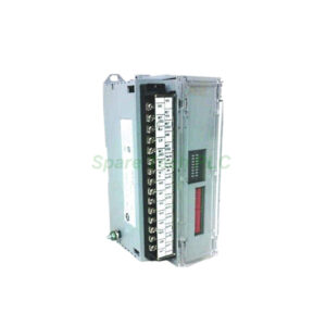
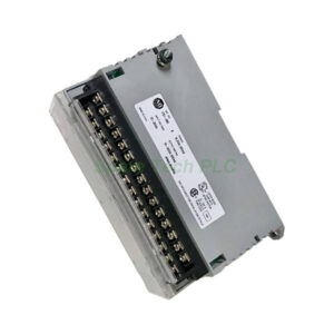
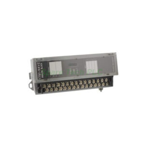
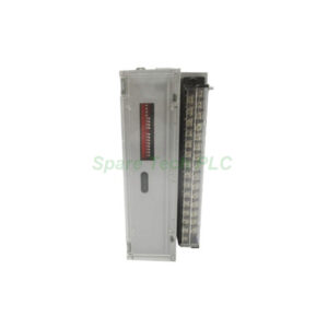
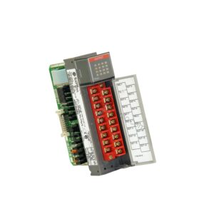
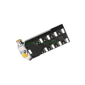
Allen-Bradley 1791-N4C2 Analog Block I/O Module with 4 Inputs and 2 Current Outputs
Product Introduction
The Allen-Bradley 1791-N4C2 is an analog Block I/O module from the 1791 series. This module features six analog points in total. Specifically, it has four analog input channels and two current output channels. The power rating for this module is 120VAC.
You can easily configure the four input channels as all voltage inputs or all current inputs. This flexibility makes the 1791-N4C2 suitable for various field devices. For instance, you can connect voltage transducers or current loop sensors without changing hardware.
This module also includes a 24VDC current-limited voltage source. This source powers loop-powered current transducers directly. Therefore, you do not need an external power supply for many common sensors.
Technical Specifications of the 1791-N4C2
The 1791-N4C2 communicates with controllers through block transfer or discrete transfer. It works with PLC-2, PLC-3, PLC-5/250, and SLC family controllers. For SLC systems, communication uses a discrete transfer process.
The analog block throughput depends on your controller's data transfer rates. After receiving output data from the controller, the analog block updates its outputs accordingly. This update occurs for each channel individually.
Input Specifications
Number of inputs: 4 (selectable)
Input configuration: All voltage OR all current
Input impedance: 10 Megohms
Absolute accuracy: 0.1% at 25°C
Update rate per channel: 10 ms
Input type: Single-ended or differential
Output Specifications
Number of outputs: 2
Output type: Current output
Output rating: 0–20 mA
Output impedance: Less than 1 ohm
Output clamping: Automatic at maximum or minimum values
Power and Environment
Power dissipation: 16.9 Watts maximum
Loop power source: 24VDC current-limited
Number of channels: 6 total (4 in, 2 out)
Understanding Output Behavior
The 1791-N4C2 has two current outputs rated for 0–20 mA operation. If your user program writes a value outside this range, the module automatically clamps the output. It clamps at the maximum value for over-range conditions. Similarly, it clamps at the minimum value for under-range conditions.
This clamping feature protects your connected field devices. However, always verify that your program stays within the 0–20 mA range for best performance.
Installation Guidelines for the 1791-N4C2
First, disconnect all power before beginning the installation. Then mount the 1791-N4C2 on a DIN rail or panel. Ensure the module is securely fastened.
Next, wire the analog inputs according to your configuration. For voltage inputs, use either single-ended or differential wiring. For current inputs, connect your 0–20 mA transducers accordingly. You can use the built-in 24VDC loop power supply for current transducers.
Then wire the two current output channels to your receiving devices. Examples include analog actuators, valve positioners, or recording instruments.
Important wiring note: You must wire blocks in series. Avoid installing any blocks in a parallel configuration. The number of blocks you can use depends on your system requirements and your controller's capacity.
Finally, connect the communication interface to your controller. Set the appropriate node address and configure the block transfer or discrete transfer method in your PLC program.
Mechanical and Environmental Parameters
The 1791-N4C2 weighs only 0.57 kg (1.25 lbs). Its compact size saves space in your control cabinet. The module dissipates up to 16.9 watts of power. Therefore, maintain adequate spacing around the module for proper airflow.
Packaging List
1 x Allen-Bradley 1791-N4C2 Analog Block I/O module
1 x Terminal block (factory-installed)
1 x Quick reference guide (printed)
No calibration certificate included
No warranty document included
Shipping Information
We ship all orders via FedEx, UPS, or DHL. Delivery typically takes 3–7 business days depending on your location.
Frequently Asked Questions (FAQ)
1. Can I mix voltage and current inputs on the same 1791-N4C2?
No. All four inputs must be configured the same way. You can set them as all voltage inputs or all current inputs. You cannot mix types on a single module.
2. What happens if my program sends a value above 20 mA to an output?
The 1791-N4C2 automatically clamps the output at the maximum value (20 mA). It will not exceed this limit. Similarly, values below 0 mA clamp at 0 mA.
3. Does the 1791-N4C2 work with SLC 500 controllers?
Yes. The module communicates with SLC family controllers through a discrete transfer process. You do not need block transfer programming for SLC systems.
4. What is the purpose of the 24VDC voltage source on this module?
This source powers loop-powered current transducers. For example, you can connect a 2-wire 4–20 mA transmitter directly. You will not need an external power supply.
5. Can I install multiple 1791-N4C2 modules in parallel?
No. You must wire blocks in series. Parallel installation is not allowed. The number of blocks depends on your system requirements and controller capacity.