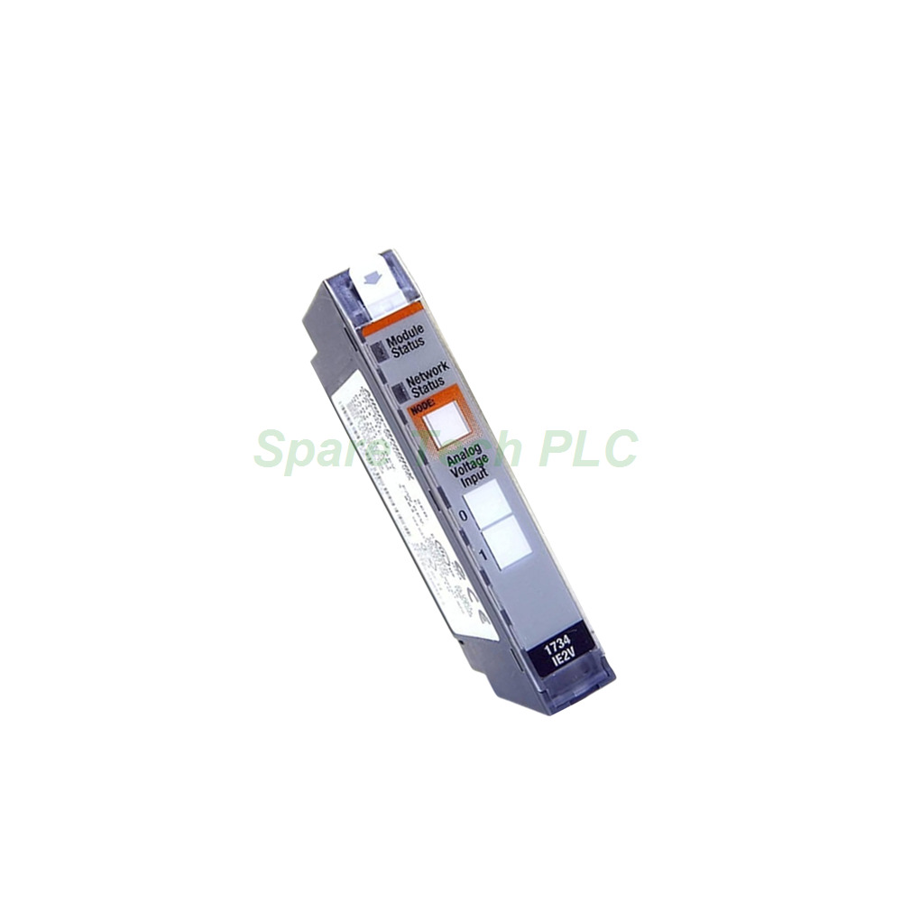
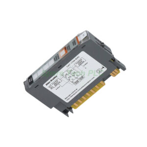
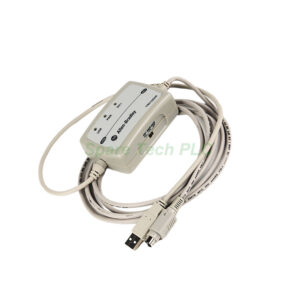
1734-IE2V 2-Channel Voltage Input Module
Product Introduction
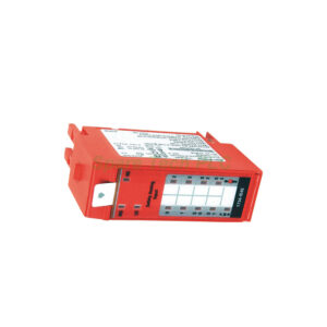
The 1734-IE2V belongs to the Allen‑Bradley POINT I/O product family and functions as a versatile analog voltage input module. It provides two single‑ended, non‑isolated voltage input channels. These channels are user‑configurable for either 0...10V or ±10V signal ranges. The module delivers 15‑bit resolution in ±10V mode and 16‑bit resolution in 0...10V mode, ensuring precise data conversion for various process variables.
Technical Specifications
The 1734-IE2V employs a Delta‑Sigma conversion type for accurate digital representation. Its absolute accuracy reaches 0.1% of full scale at 25 °C (77 °F). For the 0...10V range, it accepts inputs from ‑0.0V under to +0.5V over. For the ±10V range, it accepts inputs from ‑0.5V under to +0.5V over. The module converts external analog signals into digital values using a signed integer data format. Specifically, it generates six bytes of data, which include Channel 0 Data, Channel 1 Data, Channel 0 Status, and Channel 1 Status.
The module operates with a DC voltage range from 12 to 24 Volts DC. It dissipates 0.75 Watts of power at 28.8 Volts DC. Additionally, its thermal dissipation reaches 2.5 BTU/hour at the same voltage. This efficiency makes it suitable for dense I/O installations where heat management matters.
Input Range and Resolution
The 1734-IE2V supports both unipolar (0...10V) and ±10V operating modes. In unipolar mode, the module accepts a 0...10V input and converts it to a 16‑bit signed integer ranging from ‑32,768 to +32,767. In ±10V mode, it accepts a ±10V input and delivers a 15‑bit signed integer. This flexibility allows the module to handle various process variables such as flow, level, pressure, temperature, turbidity, conductivity, vibration, and viscosity.
Status Indicators and Diagnostics
The front panel of the 1734-IE2V includes several status indicator lights. These LEDs provide valuable diagnostic information at a glance. For instance, a steady green light indicates normal operation. A flashing green light means the module requires commissioning. Meanwhile, a flashing red light signals a recoverable fault. A steady red light indicates an irrecoverable fault. Finally, alternating flashing red and green lights mean the module is performing a diagnostic test. If none of the indicators are lit, the module is powered off.
Configurable Alarms and Input Rate
This module features latching alarms with configurable threshold levels. Specifically, you can set Low, Low Low, High, and High High alarm points. Moreover, you can disable alarms entirely if they are not needed for your application. The 1734-IE2V also allows you to adjust its input rate to match the characteristics of your process variable. For example, you can select settings for slow, medium, or fast response. Furthermore, you can tailor the rate for fluctuating or non‑fluctuating signals, or any combination of these characteristics.
Installation and Compatibility
For proper operation, you must mount the 1734-IE2V onto a compatible wiring base assembly. Suitable bases include the 1734‑TB, 1734‑TBS, 1734‑TOP, or 1734‑TOPS. During installation, set the module's keyswitch to position 3. This correct positioning prevents incorrect insertion and guarantees a secure connection.
The 1734-IE2V works with any POINT I/O communication adapter. Therefore, you can integrate it seamlessly with various networks, including ControlNet, DeviceNet, and EtherNet/IP. This module functions particularly well with ControlLogix and CompactLogix controllers. Its compact form factor and DIN rail mounting capability make it an ideal solution for remote I/O areas where space is limited and I/O counts are small to medium.
Mechanical Parameters
The 1734-IE2V has compact dimensions of 56 x 12 x 75.5 mm (2.2 x 0.47 x 2.97 in.) and weighs approximately 0.036 kg. Its open‑style enclosure makes it suitable for installation within a larger control cabinet. However, please note that this enclosure is not waterproof and does not protect against large amounts of dust or debris.
Packaging List
Your shipment will include:
One (1) Allen‑Bradley 1734-IE2V Analog Input Module
One (1) removable terminal block (if ordered with a wiring base)
Product installation instructions manual
Note: Calibration certificates and warranty information do not come with the package.
Shipping Information
All orders ship using premium express courier services. We primarily use FedEx, UPS, or DHL to ensure fast and reliable delivery worldwide.
Frequently Asked Questions (FAQ)
1. What voltage ranges does the 1734-IE2V support?
The 1734-IE2V supports both 0...10V and ±10V input ranges. You can configure the range via the software based on your application needs.
2. Which terminal base do I need for this module?
This module requires a 1734 series terminal base. Compatible bases include the 1734‑TB, 1734‑TBS, 1734‑TOP, or 1734‑TOPS.
3. What resolution does the 1734-IE2V provide?
The 1734-IE2V delivers 16‑bit resolution in unipolar mode and 15‑bit resolution in ±10V mode. This ensures accurate measurement for most industrial process variables.
4. How do the status indicators help with troubleshooting?
The LEDs on the 1734-IE2V clearly indicate the module's operational state. For example, steady green means normal, flashing red means a recoverable fault, and steady red means an irrecoverable fault. Alternating red and green indicates a diagnostic test is running.
5. Can I configure alarms on the 1734-IE2V?
Yes, the 1734-IE2V features latching alarms. You can set Low, Low Low, High, and High High thresholds. You may also disable alarms if your application does not require them.