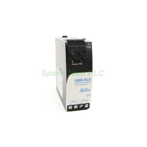
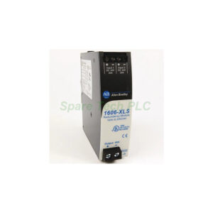
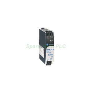
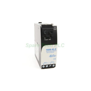
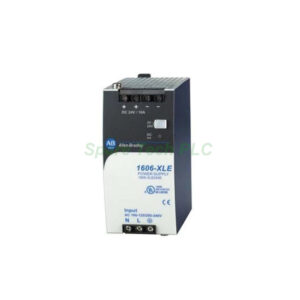
Allen-Bradley 1606-XLPRED Dual-Input Redundancy Module
Product Introduction
The 1606-XLPRED belongs to the Allen-Bradley Bulletin 1606-XL power supply accessory family. It is a dual-input diode redundancy module built for 1+1 redundant power architectures. Two separate power supplies feed the module, and internal diodes decouple their outputs. Therefore, a failure in one supply cannot drag down the shared DC bus.
This module carries a nominal output current of 10A, split as 2 × 5A inputs. It accepts a DC input range of 9...80 V and delivers a nominal DC 12...48 V output. The voltage drop across the module is only 800 mV, which preserves load voltage headroom. Furthermore, spring terminals allow fast, vibration-resistant wiring. Engineers use this unit in control systems that cannot tolerate a single power supply failure.
Technical Specifications
Electrical Parameters
The 1606-XLPRED provides two independent input channels, each rated at 5 A. Combined, the module supports 10 A nominal output current. The maximum short-circuit current reaches 16 A. Meanwhile, the input voltage range spans DC 9...80 V, covering common 12 V, 24 V, and 48 V systems.
Diode decoupling isolates the two input sources from each other. This design prevents a faulty supply from back-feeding the healthy one. The output voltage follows the higher of the two inputs, minus the 800 mV drop. Additionally, the module requires no external control wiring. It operates automatically once both supplies are connected.
Mechanical and Environmental Data
The housing measures 75 mm in height, 45 mm in width, and 81 mm in depth. It weighs approximately 140 g, making it one of the lightest modules in the Bulletin 1606 family. The 1606-XLPRED uses spring terminals for secure, screw-free connections.
Operating temperature spans -40 to +70 °C, which suits cold storage and outdoor cabinets. The protection rating is IP20 for enclosed mounting. Besides, the slim 45 mm width allows side-by-side mounting with two power supplies on the same DIN rail.
Installation Guide
First, mount the 1606-XLPRED on a standard 35 mm DIN rail near the two power supplies. Keep input wiring short to minimize voltage drop. Next, connect power supply A to input channel one and power supply B to channel two. Verify polarity carefully, because diode decoupling does not protect against reverse wiring.
After wiring both inputs, connect the common output to the load bus. Then, confirm that each supply delivers roughly half the total load current. Finally, test redundancy by switching off one supply and checking that the output remains stable. This simple test confirms correct diode operation before commissioning.
Packaging List
1 x Allen-Bradley 1606-XLPRED Redundancy Module
1 x Installation Instructions
Shipping via Fedex, UPS, or DHL
FAQ
Q1: What is the purpose of the 1606-XLPRED redundancy module?
A1: It decouples two power supplies with internal diodes. If one supply fails, the other continues feeding the load. Therefore, critical control systems avoid unexpected shutdowns.
Q2: What input and output voltages does this module support?
A2: The 1606-XLPRED accepts DC 9...80 V on each input. It delivers a nominal DC 12...48 V output. The wide range covers common 12 V, 24 V, and 48 V industrial systems.
Q3: How much current can the module handle?
A3: Each input channel carries 5 A, giving 10 A total nominal output. The maximum short-circuit current is 16 A. Additionally, the voltage drop stays at only 800 mV.
Q4: Does the module need configuration or control wiring?
A4: No, the 1606-XLPRED operates automatically. Diode decoupling requires no settings or control signals. Simply connect both supplies and the load, then verify polarity.
Q5: What are the dimensions and weight of this redundancy module?
A5: The unit measures 75 mm (H) x 45 mm (W) x 81 mm (D). It weighs approximately 140 g. The compact size allows mounting beside two standard power supplies on one DIN rail.