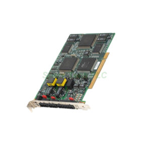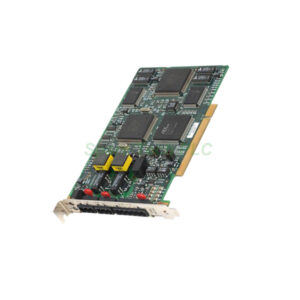
IC670MDL730 24V DC Positive Logic 16-Point Input Module – Installation & Maintenance
Product Introduction
The GE Fanuc IC670MDL730 belongs to the Series 90-70 I/O line. Specifically, it provides sixteen input points in one compact block. Each point accepts 24V DC signals. Positive logic means the input turns ON when voltage is applied. The module uses an optimal scan time for fast response. Meanwhile, the LED indicators show each point’s status clearly. You can mount this module on a standard terminal base. Additionally, the IC670MDL730 works with GE Fanuc PLC CPUs like the IC697CPU731.
Core Value
This module simplifies field wiring. Firstly, it reduces installation time. You connect one common return for all sixteen points. Secondly, the IC670MDL730 improves system reliability. Its optical isolation protects the backplane from surges. Moreover, you get true high-density input capability. This module saves rack space. Furthermore, replacement is straightforward. You do not need to remove field wiring. Consequently, downtime decreases. For applications like conveyor systems or packaging lines, the IC670MDL730 delivers consistent performance.
Technical Insights
The IC670MDL730 operates from 0°C to 60°C. Input voltage range is 10-30V DC. Nominal input current is 7mA per point. The OFF-state voltage is below 5V DC. ON-state voltage is above 11V DC. Response time is 2ms typical. Specifically, the module offers 1500Vrms isolation. The backplane current draw is 180mA at 5V DC. You must use shielded cable for long runs. Additionally, the sinking output field devices work best with this positive logic module. For noise immunity, ground the shield at one end only.

Installation & Maintenance
Follow these steps for the IC670MDL730. First, power down the PLC rack. Next, mount the base onto the DIN rail or panel. Then, insert the module into the base. Secure it with the locking screw. After that, wire field devices to the terminal block. Connect the common return to the negative side of the 24V supply. Do not exceed 30V DC. Use copper wire of 0.5-1.5mm². Tighten terminals to 0.5 Nm. Finally, apply power and check LED status. For maintenance, periodically verify input voltage at each point. Clean dust from ventilation areas. Replace the IC670MDL730 only after removing power.
Buyer’s Guide FAQ
1. What PLC systems work with the IC670MDL730?
The IC670MDL730 works with GE Fanuc Series 90-70 PLCs. Examples include the IC697CPU731, IC697CPU782, and IC697CPU772 CPUs.
2. Can I use the IC670MDL730 for 120V AC inputs?
No. The IC670MDL730 accepts only 24V DC signals. For 120V AC, use the IC670MDL640 module instead.
3. How do I troubleshoot a non-responsive channel on the IC670MDL730?
Firstly, check the LED. If OFF, measure voltage at the terminal. Ensure positive is above 11V DC. Then verify the common return connection.
4. What is the difference between positive logic and negative logic?
Positive logic means input turns ON with a high voltage (24V DC). The IC670MDL730 uses positive logic. Negative logic turns ON with 0V DC.
5. Does the IC670MDL730 support hot swapping?
No. You must power down the rack before inserting or removing the IC670MDL730. Otherwise, damage may occur.