IC200ALG230 VersaMax Analog Input Technical Maintenance Guide
Product Introduction
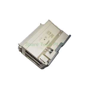
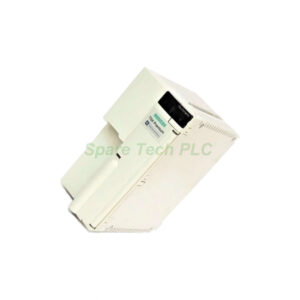
The GE Fanuc IC200ALG230 offers a compact solution for analog signal acquisition. This module directly interfaces with field transmitters. It converts 4-20 mA current signals into digital values. The PLC processor then reads these values. This module features 16 single-ended input channels. It also includes a built-in loop power supply option. The IC200ALG230 supports high-speed data updates. This capability ensures real-time process monitoring. It operates reliably in harsh industrial environments. The module fits seamlessly into the VersaMax I/O system.
Core Value
This module provides significant value for system integrators. Firstly, it reduces wiring complexity. The 16-channel design saves valuable cabinet space. Moreover, it offers high accuracy. The module provides 12-bit resolution for precise measurements. It also features user-configurable scaling. This flexibility allows direct engineering unit readouts. Consequently, it simplifies the PLC programming process. The IC200ALG230 also includes diagnostic LEDs. These indicators simplify troubleshooting. They quickly show module status and communication health. Therefore, operators can resolve issues faster. This module ensures high system uptime.
Technical Insights
Understanding the technical specifics ensures optimal performance. Specifically, the IC200ALG230 has an input range of 4-20 mA. The absolute maximum rating is 30 mA. Its input impedance is 250 ohms. The conversion uses a successive approximation method. The module updates all channels every 5 ms. This rapid update supports fast control loops. Furthermore, it offers high noise immunity. The filter attenuates high-frequency interference. This feature protects signal integrity. The module consumes 5V DC power from the backplane. Its power draw is typically 180 mA. Additionally, it supports a loop voltage of 15-18V DC. Proper grounding is essential for accurate readings. The module provides excellent common-mode rejection.
Installation & Maintenance
Proper installation maximizes the IC200ALG230's lifespan. Begin by checking the module for physical damage. Turn off system power before insertion. Align the module carefully with the backplane slot. Push firmly to seat the connector securely. Secure the module with the retaining screws. Connect the field wiring to the removable terminal block. Use shielded twisted-pair cables for inputs. Ground the cable shield at a single point. This practice reduces electrical noise. Route signal wires away from power cables. Maintain a safe distance to avoid interference. For maintenance, regularly inspect terminal connections. Look for loose wires or corrosion. Periodically verify the input signal accuracy. Use a calibrated current source for testing. Check the diagnostic LEDs frequently. A green light indicates normal operation. Replace the module if faults persist.

Buyer’s Guide FAQ
1. What type of signals does the IC200ALG230 accept?
The IC200ALG230 accepts analog current signals. It specifically handles the 4-20 mA standard. This signal comes from pressure and temperature transmitters.
2. How many channels are on this GE Fanuc module?
This module provides 16 single-ended input channels. This high density maximizes the I/O capacity per rack. Each channel operates independently for versatile applications.
3. Can I use the IC200ALG230 with other VersaMax components?
Yes, the IC200ALG230 integrates fully with the VersaMax platform. It works with compatible power supplies and CPU modules. This interoperability simplifies system expansion.
4. What should I check if the IC200ALG230 shows a fault LED?
First, check the field wiring for shorts or opens. Next, verify the power supply to the module. Finally, confirm the configuration matches your application settings. Replace the unit if these steps fail.
5. Where can I find the wiring diagram for this module?
You can find the wiring diagram in the VersaMax System User Manual. This manual provides terminal assignments and connection examples. Always refer to the official documentation for accuracy.