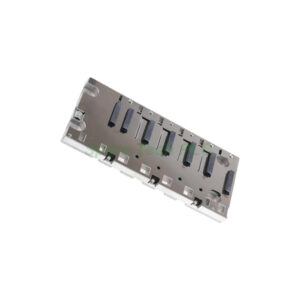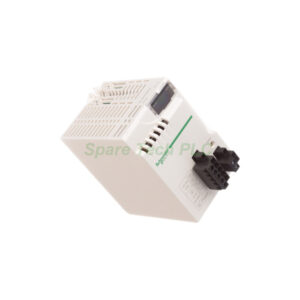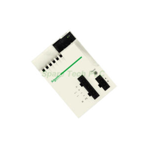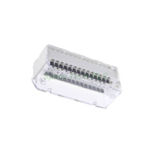
1791-8BC Block I/O Installation & Maintenance Guide
Product Introduction
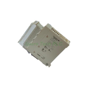
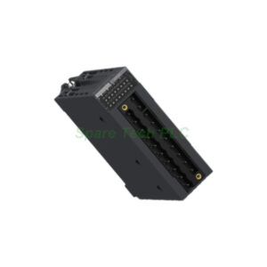
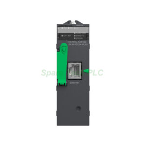
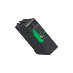
The Allen-Bradley 1791-8BC belongs to the 1791 Block I/O family from Rockwell Automation. This compact module combines eight DC sinking input channels with eight DC sourcing output channels. The integrated design eliminates the need for separate power supplies and interface modules in remote locations. The module communicates seamlessly with PLC-2, PLC-3, PLC-5, and SLC500 controllers through a Remote I/O scanner module. The Allen-Bradley 1791-8BC operates on an external 24VDC supply with a maximum current draw of 300 mA.
Core Value
The Allen-Bradley 1791-8BC delivers substantial value for distributed control architectures. Firstly, the self-contained design reduces panel space requirements significantly. The module includes built-in power supply conditioning and signal isolation circuitry. Moreover, the 1791-8BC supports RIO network distances up to 10,000 feet at 57.6K baud. This feature enables flexible placement of I/O nodes near field devices. Furthermore, the module provides thermal dissipation of only 41 BTU/hour maximum. This low heat output reduces cooling requirements in control cabinets. Besides, the 1791-8BC supports both vertical and horizontal mounting orientations. Specifically, vertical mounting allows the highest output current rating of 1A at 30°C.
Technical Insights
The Allen-Bradley 1791-8BC features eight non-isolated DC inputs in a single group. Each input circuit operates across a voltage range of 10 to 30 VDC. The inputs require a minimum of 2.5 mA at 10 VDC to guarantee an ON state. Meanwhile, the output channels provide DC sourcing capability. The output current capacity depends on mounting orientation and temperature. Specifically, vertical mounting supports 1A at 30°C, while horizontal mounting reduces the rating to 500mA.
For network communication, the 1791-8BC uses the Allen-Bradley RIO protocol. The module supports three baud rate options: 57.6K, 115.2K, and 230.4K. Network distances vary accordingly: 10,000 feet at 57.6K, 5,000 feet at 115.2K, and 2,500 feet at 230.4K. The network requires proper termination resistors. Use 150-ohm resistors for 57.6K and 115.2K baud rates. Use 82-ohm resistors for 230.4K baud. Additionally, the Allen-Bradley 1791-8BC incorporates per-channel status LEDs and a system OK indicator for easy diagnostics.
Installation & Maintenance
Proper installation of the Allen-Bradley 1791-8BC ensures reliable operation in demanding environments. Mount the module on a standard DIN rail using the integral mounting clips. For maximum output current capacity, install the module vertically. This orientation allows optimal airflow for heat dissipation. Use 14 AWG stranded copper wire for all field connections. Connect a clean 19.2 to 30 VDC power supply to the external power terminals.
For the RIO network, use Belden 9463 cable for the communication link. Connect the BLU, SHD, and CLR terminals to the scanner module. Install terminating resistors at both ends of the daisy-chain network. Maintain separation between I/O wiring and AC power lines to minimize interference. For routine maintenance, inspect terminal connections periodically. Loose connections cause intermittent faults. Check the status LEDs regularly. A steady green OK indicator confirms normal operation. Blinking or red indicators signal communication errors or power issues. Clean the module using low-pressure compressed air. Always power down before removing or inserting the module.

Buyer's Guide FAQ
Q1: What communication protocol does the Allen-Bradley 1791-8BC use?
A1: The 1791-8BC uses the Allen-Bradley Remote I/O (RIO) protocol. This protocol supports daisy-chain topologies and integrates with PLC-2, PLC-3, PLC-5, and SLC500 controllers.
Q2: What are the input specifications for the 1791-8BC?
A2: The input channels operate at 10 to 30 VDC with sinking configuration. Each input draws 2.5 to 11.0 mA. The inputs require a minimum of 2.5 mA at 10 VDC to guarantee an ON state.
Q3: What is the maximum output current for the 1791-8BC?
A3: The output current depends on mounting orientation. Vertical mounting supports 1A at 30°C and 500mA at 60°C. Horizontal mounting reduces the rating to 500mA at 30°C.
Q4: How do I troubleshoot a non-responsive 1791-8BC module?
A4: First, verify the power supply voltage is between 19.2 and 30 VDC. Check the status LEDs for error codes. Ensure the terminating resistors are correctly installed. Verify the node address switches match the scanner configuration. Inspect the Belden 9463 cable for damage. Replace the module if these steps do not restore operation.